10
As soon as the pump and driver have reached the normal
operating temperature, the unit should be shut down for
¿ nal coupling alignment. This should be done by following
the instructions found in Section B, Part 4.
After the unit has been running for about one week,
the coupling halves should be given a ¿ nal check for
misalignment caused by pipe strains or temperature
strains. If the alignment is correct, both pump and driver
may be dowelled to the baseplate if desired.
D. MAINTENANCE
1. LUBRICATION
Grease Lubricated Pump
Pump bearings are properly lubricated with grease at the
factory before shipment. Periods of subsequent lubrication
depend on local conditions, loads, speeds, hours of
operation and temperature.
Periodic inspection of bearing lubrication should be made
and additional grease added as needed. At this time the
plug in the bottom of the bearing cover should be removed
and the bearing À ushed with clean grease. A Chevron
SRI-2 or Shell Dolium “R” grease is recommended for
most installations. Do not overgrease as this causes high
bearing temperatures and shortens bearing life. The pump
should be run a short time to eject any excess grease and
the plug then replaced in the bearing cover.
Oil Lubricated Pump
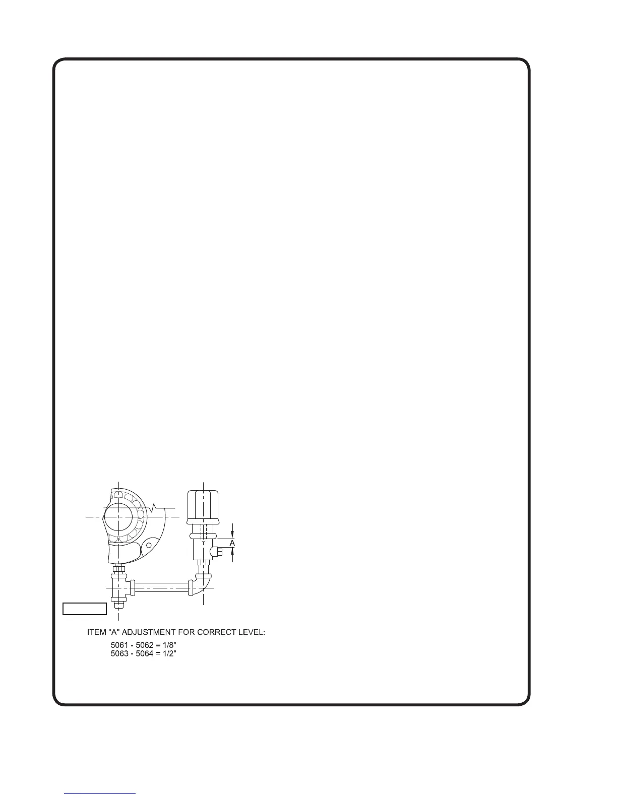
The pump is shipped without oil in the bearing housings.
Fill the reservoir to the proper level from shaft centerline as
follows:
The following lubricants are recommended at the operating
temperature indicated. See Figure 5 for correct oil levels.
0°F - 150°F, - S.A.E. #10 Wt. Non-detergent oil
150°F - 250°F, - S.A.E. #20 Wt. Non-detergent oil
Motor bearings should have periodic attention and
lubricated in accordance with the motor manufacturer’s
recommendations.
2. PACKING BOX
The packing glands should be adjusted occasionally to
insure proper packing lubrication. A slow dripping through
the gland is recommended for good lubrication and long
packing and shaft sleeve life.
When installing new rings of packing, clean packing box
and inspect parts for any damage. If the shaft sleeve is
worn or grooved, it should be replaced. New packing will
not do an adequate sealing job on a worn shaft sleeve.
Insert two new rings of packing in front of lantern ring.
Stagger joints to minimize leakage.
Tamp each ring in place. Replace lantern ring. Add two
rings of packing behind lantern ring. Replace gland and
bolts, rotate shaft and tighten gland securely. Loosen the
gland and add the ¿ nal ring of packing. Be sure lantern
ring is positioned to receive lubrication through ori¿ ce.
Tighten nuts securely to seat packing and rotate shaft.
After rotating several turns, loosen nuts to ¿ nger tight for
starting.
3. WEARING RINGS
Wearing rings are ¿ tted in the casing on all pumps and
are standard on the impeller of all pumps with 8” or larger
discharge. (Optional on smaller units). These wearing rings
provide a close running clearance, to reduce the quantity
of liquid leaking from the high pressure side to the suction
side. These rings depend on the liquid in the pump for
lubrication. They will eventually wear so that the clearance
becomes greater and more liquid passes into the suction.
This rate of wear depends on the character of the liquid
pumped. When worn excessively these rings will cause
the pump to loose ef¿ ciency and should be replaced.
Recommended wear ring clearances are as follows:
Model C.I. or Bz. Stainless Steel
5061 .009/.014 .019/.024
5062 .011/.016 .021/.026
5063 .013/.018 .023/.028
5064 .016/.023 .029/.036
4. DISASSEMBLY
The following procedure is for complete disassembly of the
pump. If complete disassembly is not necessary, use only
those steps which apply.
a. Disconnect coupling from driver before proceeding.
b. Disconnect seal water lines (if used). Remove oiler
piping on oil lube pumps.
c. Remove split gland and clips.
d. Remove bolts and nuts and lift off upper half casing
(1B).
e. Remove gasket (73) and soak in water.
f. Match mark and remove bearing caps (41) and (43).
g. Lift out rotating element.
h. Remove bearing caps.
i. On grease lubricated pumps, open tangs of bearing
lockwasher (69), unscrew and remove bearing lock
nut (22). Remove lockwasher. For oil lubricated
pumps, remove both oil rings (60). Unscrew and
remove both bearing lock nuts (22).
Figure 5
 Loading...