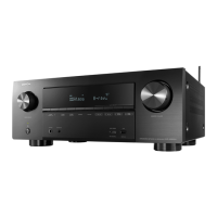
Terminal Functions
Pin Name Type Description Alternative Function
1 ADIN1 I ADC analog input[1]
2 ADIN0 I ADC analog input[0]
3 AVDD33 P ADC Analog Power supply (3.3V)
4 AVSS33 P ADC Analog Ground
5 GP00 BD General Purpose IO 00 External Interrupt 0
6 GP01 BD General Purpose IO 01 External Interrupt 1
7 D0 B External SDRAM data bus [0] External program data bus [0]
8 D8 B External SDRAM data bus [8] External program data bus [8]
9 D1 B External SDRAM data bus [1] External program data bus [1]
10 D9 B External SDRAM data bus [9] External program data bus [9]
11 D2 B External SDRAM data bus [2] External program data bus [2]
12 D10 B External SDRAM data bus [10] External program data bus [10]
13 D3 B External SDRAM data bus [3] External program data bus [3]
14 VDD12 P Digital power supply (1.2V)
15 VSS12 P Digital Ground
16 NC Not Connected
17 D11 B External SDRAM data bus [11] External program data bus [11]
18 D4 B External SDRAM data bus [4] External program data bus [4]
19 D12 B External SDRAM data bus [12] External program data bus [12]
20 D5 B External SDRAM data bus [5] External program data bus [5]
21 D13 B External SDRAM data bus [13] External program data bus [13]
22 D6 B External SDRAM data bus [6] External program data bus [6]
23 D14 B External SDRAM data bus [14] External program data bus [14]
24 D7 B External SDRAM data bus [7] External program data bus [7]
25 D15 B External SDRAM data bus [15] External program data bus [15]
26 AD0 O External SDRAM address bus [0] External program address bus [0]
27 AD1 O External SDRAM address bus [1] External program address bus [1]
28 AD2 O External SDRAM address bus [2] External program address bus [2]
29 IOVDD33 P I/O Power supply (3.3V)
30 IOVSS33 P I/O Ground
31 AD3 O External SDRAM address bus [3] External program address bus [3]
32 AD4 O External SDRAM address bus [4] External program address bus [4]
33 AD5 O External SDRAM address bus [5] External program address bus [5]
34 AD6 O External SDRAM address bus [6] External program address bus [6]
35 AD7 O External SDRAM address bus [7] External program address bus [7]
36 AD8 O External SDRAM address bus [8] External program address bus [8]
37 AD9 O External SDRAM address bus [9] External program address bus [9]
38 AD10 O External SDRAM address bus [10] External program address bus [10]
39 AD11 O External SDRAM address bus [11] External program address bus [11]
40 AD12 O External SDRAM address bus [12] External program address bus [12]
41 BA0 O External SDRAM Bank selector 0 External program address bus [13]
42 BA1 O External SDRAM Bank selector 1 External program address bus [14]
43 LDQM O SDRAM Lower byte data mask External program address bus [15]
44 UDQM O SDRAM Upper byte data mask External program address bus [16]
45 SDCSN O SDRAM Chip select
46 VDD12 P Digital power supply (1.2V)
47 VSS12 P Digital Ground
48 CKE O SDRAM clock enable
49 RASN O SDRAM RAS
50 IOVDD33 P I/O Power supply (3.3V)
51 IOVSS33 P I/O Ground
52 SDCLK O SDRAM clock
53 CASN O SDRAM CAS
54 WEN O SDRAM WEN
55 EAD17 B External memory address[17] General Purpose IO 37
56 EAD18 B External memory address[18] General Purpose IO 38
57 EAD19 B External memory address[19] General Purpose IO 39
58 EAD20 B External memory address[20]
General Purpose IO 40
Boong Mode
59 EWEN B External memory WEN General Purpose IO 41
60 EOEN B External memory OEN General Purpose IO 42
61 ECSN O External memory CSN
62 GP03 B General Purpose IO 03 External Clock (16.9344MHz)
63 GP04 B General Purpose IO 04 SPI0 CS
64 GP05 B General Purpose IO 05 SPI0 CK
65 GP06 B General Purpose IO 06 SPI0 MISO
66 GP07 B General Purpose IO 07 SPI0 MOSI
67 GP08 B General Purpose IO 08 HUART0 DI
68 GP09 B General Purpose IO 09 HUART0 DO
69 GP10 B General Purpose IO 10
HUART0 RTS
External Interrupt 11
70 GP11 B General Purpose IO 11
HUART0 CTS
External Interrupt 12
71 GP12 B General Purpose IO 12
Chip Select 1
When GP12 is used for CS1, the external
pull-up resistor (48 kΩ) has to be connected
with this pin
72 GP13 B General Purpose IO 13
UART0 RX Data
External Interrupt 8
73 GP14 B General Purpose IO 14
UART0 TX Data
External Interrupt 9
74 GP15 B General Purpose IO 15
UART1 RX Data
I2C SCL
75 GP16 B General Purpose IO 16
UART1 TX Data
I2C SDA
76 GP17 B General Purpose IO 17 SPI1 CS
77 GP18 B General Purpose IO 18 SPI1 CK
Before Servicing
This Unit
Electrical Mechanical Repair Information Updating
44
 Loading...