1. IC's
SEMICONDUCTORS
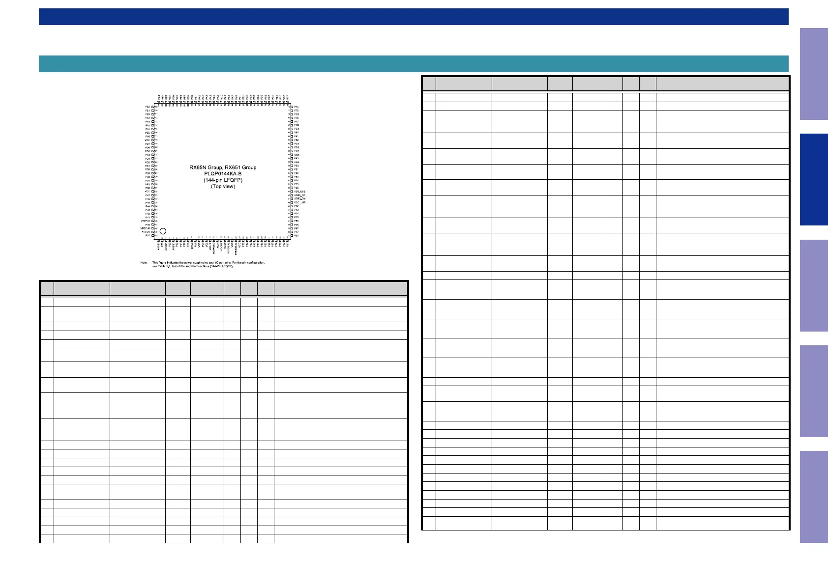
R5F5651EDDFB (DIGITAL_MCU : IC751)
R5F5651EDDFB Terminal Functions
Pin Pin Name Symbol I/O Pu/Pd STBY STOP
CEC
STBY
Function
1 AVSS0 AVSS - - - - Ground pin
2 P05/IRQ13 POWER_KEY I M3VPu I I I
Detect Power switch (Release from Wait Mode,Set
to interrupt)
3 AVCC1 AVCC - - - - Power supply pin
4 P03/IRQ11 RED_LED O L/H L H POWER/STANDBY LED control pin
5 AVSS1 AVSS - - - - Ground pin
6 P02/IRQ10/AN120
SB_RL (X1600H/S750H)/
NC (S650H)
O L L L Speaker relay control pin
7
P01/RXD6/IRQ9/
AN119
RXD_MI232O I M3VPu I I I
External data input port (for AMX/FW update via
232C) :Connector is FFC
8
P00/TXD6/IRQ8/
AN118
TXD_MO232I O L L L
External data output port (for AMX/FW update via
232C) :Connector is FFC
9 PF5/IRQ4
WHITE_LED
(X1600H(NA) /GREEN_
LED (X1600H (EU/CH/
JP) /S750H/S650H)
O L L L POWER LED control pin
10 EMLE EMLE I Pd - - -
E20 Emulator control pin (On chip Emulator is
used,this pin should be High. Not used,it should
be Low)
11 PJ5 VSEL_A I SW3VPu I I I Master volume (Rotary encoder) signal input pin
12 VSS VSS - - - - Ground pin
13 PJ3 VSEL_B I SW3VPu I I I Master volume (Rotary encoder) signal input pin
14 VCL VCL I - - - Smoothing capacitor connection pin
15 VBATT VBATT - - - - Power supply pin
16 MD/FINED MD I M3VPu I I I
Pins for setting the operating mode(select the
Boot Mode or User Boot Mode,Single Chip Mode)
17 XCIN XCIN I Pd - - - NC(Pull down)
18 XCOUT XCOUT I - - - NC(open)
19 RES# RESET I - - - Reset signal input pin
20 XTAL/P37 XTAL I - - - Pins for a crystal resonator (Xin=12MHz × 10)
21 VSS VSS - - - - Ground pin
Pin Pin Name Symbol I/O Pu/Pd STBY STOP
CEC
STBY
Function
22 EXTAL/P36 EXTAL - - - - Pins for a crystal resonator (Xin=12MHz × 10)
23 VCC VCC - - - - Power supply pin.
24 UPSEL/P35(IN)/NMI DSP_FLAG0 I
DA3VPu
(X1600/S750)
/Pd (S650)
L L L
DSP(CS49844A) interrupt signal input
pin(X1600H/S750H) / DSP(ADI) interrupt signal
input pin(S650H)
25
TRST#/P34/SCK6/
SCK0//IRQ4
TRST#/
NC(NORMRAL)
I/I Pd I/I I/I I/I
E20 Emulator control pin/When normal operating
mode,set to input.
26
P33/TIOCD0/RXD6/
RXD0/IRQ3-DS
RC_IN I Pd I I I Remote input
27
P32/TXD6/TXD0/
IRQ2-DS
BDOWN I M3VPu I I I Detect power down
28 TMS/P31/IRQ1-DS TMS/NC(NORMRAL) I/I M3VPu -/I -/I I
E20 Emulator control pin/When normal operating
mode,set to input.
29
TDI/P30/RXD1/
IRQ0-DS
TDI/RXD_MITSUBI-
SHI
I/O/I M3VPu -/-/I -/-/I I
E20 Emulator control pin/Mitsubishi writter
control pin/When normal operating mode,set to
input.
30
TCK/FINEC/P27/
SCK1/
TCK/NC(NORMRAL) I/I/I M3VPu -/-/I -/-/I I
E20 Emulator control pin//When normal operat-
ing mode,set to input.
31 TDO/P26/TXD1
TDO/TXD_MITSUBI-
SHI
O/O/I M3VPu -/-/I -/-/I I
E20 Emulator control pin/Mitsubishi writter
control pin/When normal operating mode,set to
input.
32 P25/RXD3 ADV7623_RST O Pd L L L
HDMI transceiver w/ GUI(ADV7623) reset control
pin
33 P24/SCK3 MVOL_MUTE O L L L Volume control pin (NJU72343)
34 P23/TXD3 E_RTS_MOEI O
Pd
(BCM58305
Internal Pd)
L L L Ethernet(Network Module) control pin
35 P22/SCK0 E_CTS_MIEO I
Pd (onboad
+ BCM58305
Internal Pd)
I I I Ethernet(Network Module) control pin
36 P21/RXD0/IRQ9 E_RXD_MIEO I
Pd (onboad
+ BCM58305
Internal Pd)
I L I Ethernet(Network Module) control pin
37 P20/TXD0/IRQ8 E_TXD_MOEI O
Pd
(BCM58305
Internal Pd)
L L L Ethernet(Network Module) control pin
38
P17/SCK1/TXD3/
IRQ7
NET_FACT_RST O(ODR)
Pu
(BCM58305
Internal Pu)
Z Z Z Ethernet(Network Module) control pin
39 P87 7623_ROM_HOLD O L L L Flash ROM for GUI control pin
40
P16/TXD1/RXD3/
IRQ6
TU_SCLK O L L L TUNER control
41 P86
PRE_Z2_MUTE (X1600H
(NA)) /NC (X1600H (EU/
CH/JP)/S750H/S650H)
O L L L Mute for zone preout control pin
42 P15/RXD1/IRQ5 TU_SDIO I_O L L L TUNER control
43 P14/IRQ4 VEXP_OE O L L L Expander (MC74HC4094) control pin
44 P13/TXD2/IRQ3 VEXP_CLK O L L L Expander (MC74HC4094) control pin
45 P12/RXD2/IRQ2 VEXP_DATA O L L L Expander (MC74HC4094) control pin
46 VCC_USB VCC_USB - - - - Power supply pin
47 USB0_DM USB0_DM - - - - NC(open)
48 USB0_DP USB0_DP - - - - NC(open)
49 VSS_USB VSS_USB - - - - Ground pin
50 P56 TU_SEN O L L L TUNER control pin
51 P55/IRQ10 VEXP_STB O L L L Expander (MC14094) control pin
52 P54 NET5V_POWER O L L L Ethernet power supply (Net5V) control pin/
53 BCLK/P53
DSP_BSY (X1600H/
S750H) /NC (S650H)
I DA3VPu I I I DSP BUSY signal input
Only major semiconductors are shown, general semiconductors etc. are omitted to list.
The semiconductor which described a detailed drawing in a schematic diagram are omitted to list.
Before Servicing
This Unit
Electrical Mechanical Repair Information Updating
44

 Loading...