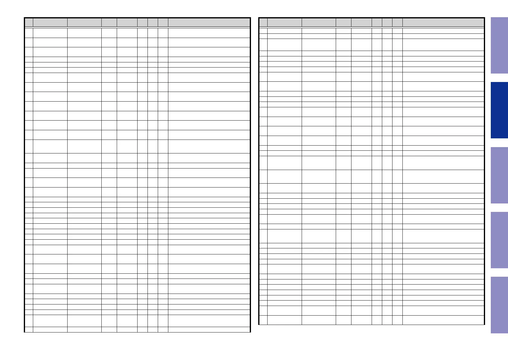
Pin Pin Name Symbol I/O Pu/Pd STBY STOP
CEC
STBY
Function
54 P52/RXD2 ADV7623_SPI_MI I L L L
HDMI transceiver w/ GUI(ADV7623) control pin
(for GUI)
55 P51/SCK2 ADV7623_SPI_CLK O L L L
HDMI transceiver w/ GUI(ADV7623) control pin
(for GUI)
56 P50/TXD2 ADV7623_SPI_MO O L L L
HDMI transceiver w/ GUI(ADV7623) control pin
(for GUI)
57 VSS VSS - - - - Ground pin
58 P83 ARC_RST O L L L Reset control pin for ARC IC
59 VCC VCC - - - - Power supply pin.
60 PC7/TXD8/IRQ14 UB I Pd - - -
Pins for setting the boot mode(select the Boot
Mode or User Boot Mode)
61 PC6/RXD8/IRQ13 HSCL_(400k) O
CEC3V/
DV3Pu
L L L VIDEO I2C(SCL) control ADV7623 / Sil9437
62 PC5/SCK8 HSDA_(400k) I_O
CEC3V/
DV3Pu
L L L VIDEO I2C(SSA) control ADV7623 / Sil9437
63 P82/TXD10 DSP_MOSI O DA3VPu L L L
DSP(CS49844A) control pin(X1600H/S750H) /
DSP(ADI) control pin(S650H)
64 P81/RXD10 DSP_MISO I DA3VPu L L L
DSP(CS49844A) control pin(X1600H/S750H) /
DSP(ADI) control pin(S650H)
65 P80/SCK10 DSP_CLK O DA3VPu L L L
DSP(CS49844A) control pin(X1600H/S750H) /
DSP(ADI) control pin(S650H)
66 PC4/SCK5 DSP_CS O DA3VPu L L L
DSP(CS49844A) control pin(X1600H/S750H) /
DSP(ADI) control pin(S650H)
67 PC3/TXD5
DSP_ROM_
WRITE(X1600H/
S750H)/NC(S650H)
O L L L
DSP ROM writing control(When writing,set to
High)
68 P77/TXD11 DSP_RST O
Pd (S750/
X1600)
L L L
DSP(CS49844A) reset control pin(X1600H/S750H)
/ DSP(ADI) reset control pin(S650H)
69 P76/RXD11 SEL_DATA O L L L Audio selector control pin for NJU72750
70 PC2/RXD5 DA_POWER O L L L
Digital audio power supply (DA3.3V,DA1.2V)
control pin
71 P75/SCK11 CEC_POWER2 O L L H
CEC standby power control (for CEC Standby
Mode 3)
72 P74 ADV7623_SPI_CS O L L L
HDMI transceiver w/ GUI(ADV7623) control pin
(for GUI)
73 PC1/SCK5/IRQ12 DAC_PLD_ERR I Pd L L L Detect DAC/PLD error (from Audio PLD and DAC)
74 VCC VCC - - - - Power supply pin.
75 PC0/IRQ14 H/P_RL O L L L Headphone relay control pin
76 VSS VSS - - - - Ground pin
77 P73 FRONT_RL O L L L Speaker relay control pin
78 PB7/TXD9 PSDA I/O CEC3VPu O/L L L HDMI I2C (MN864788/787) control pin
79 PB6/RXD9 PSCL I/O CEC3VPu O/L L L HDMI I2C (MN864788/787) control pin
80 PB5 SEL_CLK O L L L Audio selector control pin for NJU72750
81 PB4 APLD_CS O L L L Audio PLD (5M570ZF256C5N) control pin
82 PB3/SCK4/SCK6
APLD_DATA/DAC_
DATA
O/O L L L
Audio PLD (5M570ZF256C5N) control pin/DAC
(AK4458VN) control pin
83 PB2
APLD_CLK/DAC_
CLK
O/O L L L
Audio PLD (5M570ZF256C5N) control pin/DAC
(AK4458VN) control pin
84
PB1/TXD4/TXD6/
IRQ4-DS
DAC_MS O L L L DAC (AK4458VN) control pin
85 P72 DAC_RST O L L L DAC (AK4458VN) control pin
86 P71 PRE_MUTE O L L L MUTE for preout control pin
87
PB0/RXD4/RXD6/
IRQ12
ARC_INT I IOVcc3VPu L L L ARC IC interrupt signal input pin
88 PA7 ISEL_A I SW3VPu I I I Input selector (Rotary encoder) signal input pin
89 PA6 ISEL_B I SW3VPu I I I Input selector (Rotary encoder) signal input pin
90 PA5 C/S_RL O L L L Speaker relay control pin
91 VCC VCC - - - - Power supply pin.
92 PA4/TXD5/IRQ5-DS
ZVOL_DATA (X1600H
(NA)/NC (X1600H (EU/
CH/JP)/S750H/S650H)
O L L L ZONE volume(BD3812) control pin
93 VSS VSS - - - - Ground pin
Pin Pin Name Symbol I/O Pu/Pd STBY STOP
CEC
STBY
Function
94 PA3/RXD5/IRQ6-DS MVOL_DATA O L L L Volume control pin (NJU72343)
95 PA2/RXD5 MVOL_CLK O L L L Volume control pin (NJU72343)
96
PA1/MTIOC0B/
IRQ11
ZVOL_CLK (X1600H
(NA)/NC (X1600H (EU/
CH/JP)/S750H/S650H)
O L L L ZONE volume(BD3812) control pin
97 PA0 H5V_DET I Pd I I I HDMI IN 5V detect signal pin
98 P67/IRQ15 FL_CE O L L L FL display control pin
99 P66 FL_DATA O L L L FL display control pin
100 P65 FL_CLK O L L L FL display control pin
101 PE7/IRQ7/AN105 KEY3 I M3VPu I I I
Key control signalinput pin (When standby
mode,set to inturrupt)
102 PE6/IRQ6/AN104 KEY2 I M3VPu I I I
Key control signalinput pin (When standby
mode,set to inturrupt)
103 VCC VCC - - - - Power supply pin.
104 P70 Hi-B_RL O L L L HIGH-B relay control pin
105 VSS VSS - - - - Ground pin
106 PE5/IRQ5/AN103 KEY1 I M3VPu I I I
Key control signalinput pin (When standby
mode,set to inturrupt)
107 PE4/AN102 DC_DET/ASO I SW3VPu I I I
Protection detect signal input pin (for DC and
ASO) (A/D converter)
108 PE3/AN101
AMPSIGDET
(S750H/X1600H)
I Pd I L I Signal level monitor pin (AD converter)
109
PE2/RXD12/IRQ7-
DS/AN100
CURRENT_DET I Pd I L I Current level monitor pin (A/D converter)
110 PE1/TXD12 THERMAL_B I SW3VPu I L I Protection detect signal input pin
111 PE0/SCK12 NET3.3V_POWER O L L L Ethernet power supply control(Net3.3V)
112 P64 D5V_POWER (NC) O L L H
Digital 5V power supply control pin(3.3V and 1.8V
generate from 5V)(When CEC standby mode3,set
to Low)
113 P63 CEC_POWER O L L H
CEC standby power supply
control(CEC5V,CEC3.3V,CEC1.8V)(When CEC
standby mode3,set to Low)
114 P62 DV_POWER1 O L L L
Digital video power supply (DV5V,DV3.3V) control
pin
115 P61 DIR_DOUT I DA3VPu I I I DIR (PCM9211) control pin
116 VSS VSS - - - - Ground pin
117 P60 DIR_DIN O L L L DIR (PCM9211) control pin
118 VCC VCC - - - - Power supply pin.
119 PD7/IRQ7/AN107 H/P_DET/MIC_DET I SW3VPu I I I
Headphone insert detect pin/Microphone insert
detect pin (A/D converter)
120 PD6/IRQ6/AN106 MODE I I I I Region setting pin
121 PD5/IRQ5/AN113
DA_POWER2
(X1600H/S750H)/
NC (S650H)
O L L L Digital audio power supply (D1.0V) control pin
122 PD4/IRQ4/AN112 DIR_RST O Pd L L L DIR (PCM9211) control pin
123 PD3/IRQ3/AN111 MN864788_HINT I CEC3VPu I I I HDMI Tx (MN864788) interrupt signal input pin
124 PD2/IRQ2/AN110 MN864787_HINT I CEC3VPu I I I HDMI Rx (MN864787) interrupt signal det
125 PD1/IRQ1/AN109 TU_GPO2_INT I L L L TUNER control pin
126
PD0/TIOCA7/IRQ0/
AN108
CEC_IN I SW3VPu I I I CEC-D control pin
127 P93/AN117 THERMAL_A I SW3VPu I L I Protection detect signal input pin
128 P92/RXD7/AN116 TEMP_SENSOR I NET3.3VPu I L I Temperature sensor input pin (for SRM)
129 P91/SCK7/AN015
TU_RST
O L L L TUNER control
130 VSS VSS - - - - Ground pin
131 P90/TXD7/AN114 H5VOUT_POWER O L L L HDMI 5V power supply control pin
132 VCC VCC - - - - Power supply pin.
133
P47/IRQ15-DS/
AN007
FL_RST O L L L FL display control pin
134
P46/IRQ14-DS/
AN006
DIR_CE O L L L DIR (PCM9211) control pin
Before Servicing
This Unit
Electrical Mechanical Repair Information Updating
45

 Loading...