Do you have a question about the Denon DR-M2 and is the answer not in the manual?
Controls the power ON/OFF state of the set.
Used for unattended recordings or wake-up playback.
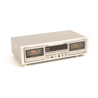
Opens the cassette compartment.
Area where the cassette tape is loaded.
Displays tape counter and remaining tape time.
Activates Dolby NR system and selects B or C type.
Prevents Dolby NR mis-operation during FM recordings.
Selects SOURCE or TAPE for monitoring.
Indicates peak recording/playback level.
Shows selected tape type (NORMAL, CrO2, METAL).
Adjusts headphone and monitor output volume.
Displays selected Dolby NR system (B or C).
Indicates selected monitor source (TAPE or SOURCE).
Adjusts the record input level for L and R channels.
Buttons for PLAY, STOP, REWIND, FAST FORWARD, RECORD, PAUSE/MUTE.
Automatically sets equalizer and recording sensitivity.
Shows the overall system block diagram for DR-M3.
Shows the overall system block diagram for DR-M2.
Illustrates signal levels during playback.
Illustrates signal levels during recording.
Explains the function of the mechanism control microcomputer.
Details the function of the computer counter.
Explains the automatic tuning system.
Step-by-step guide to detach the front panel.
Steps for removing the main mechanical assembly.
Instructions for removing the main control PCB.
Procedure for removing the FL meter unit.
Procedure for removing the FL counter unit.
Steps to remove the CTS circuit board (DR-M3).
Guide for detaching the audio circuit board.
Steps to remove the logic circuit board.
Procedure for removing the power supply board.
Instructions for replacing the pinch roller.
How to measure pinch roller pressure.
Steps for replacing the R/P head.
Procedure for R/P head height and azimuth adjustment.
Steps for replacing the erase head.
How to set the erase head height.
Setting the tension arm gap.
Verifying capstan shaft axial movement.
Measuring take-up torque.
Setting reel thrust movement within tolerance.
Verifying tape path and guide alignment.
Setting the azimuth alignment of the R/P head.
Adjusting tape speed using a frequency counter.
Setting input signal levels.
Verifying Dolby system frequency response.
Setting playback level and frequency response.
Calibrating the FL meter display.
Setting record/playback frequency response.
Adjusting the Computer Tuning System.
List of all parts for the mechanism unit.
List of parts corresponding to exploded views.
Lists of parts for various component units (Audio, CTS, FL Meter, etc.).
Visual breakdown of the mechanism components.
Visual breakdown of the cabinet and chassis.
Printed wiring board layout for the Audio Amplifier Unit.
Printed wiring board layout for the CTS Unit.
Printed wiring board layout for the FL Meter Unit.
Printed wiring board layout for the FL Meter Unit (DR-M2).
Printed wiring board layout for the Logic/Power Unit.
Printed wiring board layout for the FL Counter Unit.
Printed wiring board layout for the Control Unit.
Printed wiring board layout for the Capstan Servo Unit.
Illustrates interconnections between printed wiring boards.
Circuit diagram for the Audio Amplifier Unit.
Circuit diagram for the CTS Unit.
Circuit diagram for the FL Meter Unit.
Circuit diagram for the Logic and Power Unit.
Circuit diagram for the FL Counter Unit.
Circuit diagram for the Capstan Servo Unit.
Circuit diagram for the Control Unit.
| Track System | 4-track, 2-channel stereo |
|---|---|
| Heads | 1 x record/playback, 1 x erase |
| Motor | DC Servo Motor |
| Noise Reduction | Dolby B, C |
| Type | Cassette Deck |
| Tape Type | CrO2, Metal |
| Frequency Response | 20 Hz - 20 kHz |
| Wow and Flutter | 0.05% (WRMS) |
| Input | Line Level |
| Power Supply | 220V |
| Signal-to-Noise Ratio | 72dB (Dolby C) |
| Output | Line Level |