Do you have a question about the Denon DR-M22 and is the answer not in the manual?
Safety warnings regarding component replacement and leakage current testing.
Overall functional block diagram of the cassette deck.
Signal level flow diagram for playback and recording systems.
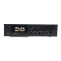
Controls AC power to the deck.
For use with optional audio timer for unattended recording/playback.
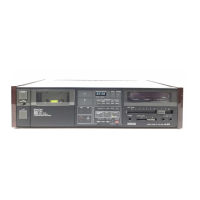
Press to eject cassette. Stop tape first if operating.
Must be closed for transport controls to operate.
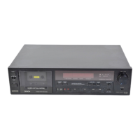
Four-digit readout indicating tape count position.
Activates/deactivates Dolby NR and selects B/C type.
Selects SOURCE or TAPE monitoring.
Adjusts bias for NORMAL and CrO2 tape.
Indicate recording or playback peak levels.
Indicates tape type selected by Auto Tape Select.
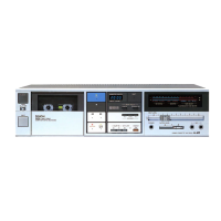
Adjusts playback, recording monitor, and headphone levels.
Informs Dolby NR status (B or C type).
Informs selected monitoring source (TAPE or SOURCE).
Adjust recording levels for each channel.
For private listening or monitoring via headphones.
Resets the tape counter to zero.
Stops tape at '0000' counter point during rewind.
Detailed explanation of all tape transport operational keys.
Explanation of the microcomputer's role in controlling the tape deck mechanism.
Step-by-step guide for disassembling various parts of the cassette deck.
Procedures for adjusting and checking mechanical parts like pinch rollers and heads.
Procedures for adjusting electrical components and overall frequency response.
Circuit diagram for the power supply and logic control sections.
Printed wiring board layout for the power and logic unit.
Circuit diagram for the audio amplification stage.
Printed wiring board layout for the audio amplifier unit.
Circuit diagram for the tape counter and meter display units.
Printed wiring board layout for the counter meter unit.
Circuit diagram for the main control functions.
Visual breakdown of the cassette mechanism components.
Visual breakdown of the external cabinet and chassis assembly.
Component list for the KU-5350 Audio Unit.
Component list for the Mechanism 85 Unit.
Component list for the KU-5371 Counter/Meter Unit.
Component list for the KU-5100 Mechanism P.W.B Unit.
Parts related to carton case packaging.
Component list for the KU-5361 Power and Logic Unit.
Diagram illustrating all P.W. board interconnections and external component wiring.
| Type | Cassette Deck |
|---|---|
| Track System | 4-track, 2-channel stereo |
| Tape Speed | 4.76 cm/s |
| Heads | 1 x record/playback, 1 x erase |
| Tape Type | CrO2, Metal |
| Noise Reduction | Dolby B |
| Output | Line |
| Inputs | 1 x RCA |
| Outputs | 1 x RCA |
| Signal to Noise Ratio | 72dB (Dolby C) |