EasyManua.ls Logo

Denon DR-F7 User Manual

Denon DR-F7
65 pages
To Next Page IconTo Next Page
Page #1 background imageLoading...
Page #1 background image
ΡΕΝΟΝ
mee.
|
SERVICE
MANUAL
ait
=
STEREO
CASSETTE
TAPE
DECK
Q
MopeL
DR-F6/F7/F8
DR—F6
1
DR—F7/F8
NIPPON
COLUMBIA
CO.
LTD.
Question and Answer IconNeed help?

Do you have a question about the Denon DR-F7 and is the answer not in the manual?

Denon DR-F7 Specifications

General IconGeneral
BrandDenon
ModelDR-F7
CategoryTape Deck
LanguageEnglish

Summary

Denon Service Manual Overview

Main Features

Key features of the Denon Hi-Fi Component stereo cassette tape deck.

Technical Specifications

Detailed technical specifications for the tape deck models.

Denon Tape Deck Controls and Components

Front Panel Controls and Indicators

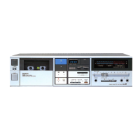
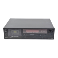
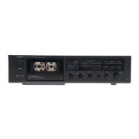
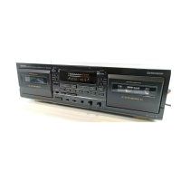
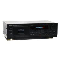
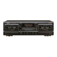
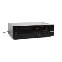
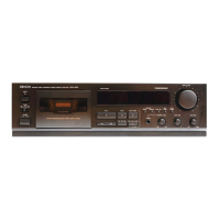
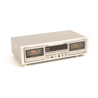
Identification and function of front panel buttons, switches, and meters.

Input/Output Jacks and Tape Controls

Details on microphone/headphone jacks and tape operation buttons.

Denon Tape Deck System Diagrams

DR-F6 Block and Level Diagrams

Block and level diagrams for the DR-F6 model.

DR-F7/F8 Block and Level Diagrams

Block and level diagrams for the DR-F7/F8 models.

Denon FTS (Flat Tuning System) Operation

FTS Function Outline

Explains the step-by-step operation of the FTS system.

FTS Microprocessor Functions

Details the main functions of the FTS microprocessor.

Denon Tape Deck Maintenance Procedures

Disassembly Instructions

Step-by-step guide for disassembling the tape deck.

Mechanism Section Adjustments

Procedures for adjusting and checking mechanical parts.

Electrical Section Adjustments

Guides for adjusting various electrical sections and controls.

Denon Tape Deck Parts Lists

Mechanism and Exploded View Parts

Lists for mechanism unit and parts from exploded views.

Circuit Board and Accessory Parts

Parts lists for specific circuit boards and accessories.

Denon Tape Deck Schematics and PC Board Layouts

PC Board Connection Diagrams

Wiring diagrams showing PC board connections for DR-F6 and DR-F7/F8.

Logic, Power, and Audio Schematics

Schematic diagrams for logic, power, and audio units.

Dolby, Detector, and Wiring Unit Schematics

Schematics for Dolby amp, leader detector, and wiring units.

Specific Unit Board Layouts

PC board layouts for DD, leader detector, and quartz lock units.

Related product manuals