14
Rear panel
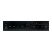
n PMA-720AE
ui
t yq w e r
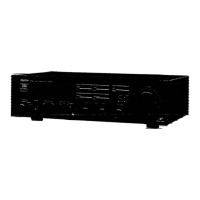
n PMA-520AE
ui
t yq w r
q Input connectors (INPUTS) ······················································· (4)
w Input/output connectors (Recordings)
(RECORDER) ············································································· (10)
e PRE OUT connectors ································································· (7)
r Speaker system terminals
(SPEAKER SYSTEMS) ······························································· (4)
t AC OUTLET ················································································ (8)
y Power cord ················································································· (8)
u REMOTE CONTROL jacks
Extension jack for future use.
i SIGNAL GND (ground) terminal ·············································· (7)
NOTE
•This terminal is not a safety ground.
•The SIGNAL GND terminal of this unit is not a safety ground
connection. Connect it to reduce noise when noise is excessive.
Note that depending on the record player, connecting the ground
line may have the reverse effect of increasing noise. In this case,
it is not necessary to connect the ground line.
 Loading...