9
DISASSEMBLY
• Disassemble in order of the arrow in the following gure.
• In the case of the re-assembling, assemble it in order of the reverse of the following ow.
• In the case of the reassembling, observe "Caution concerning disassembly and assembly!".
• If wire bundles are untied or moved to perform adjustment or replace parts etc., be sure to rearrange them neatly as
they were originally bundled or placed afterward.
Otherwise, incorrect arrangement can be a cause of noise generation.
About the photos used for "descriptions of the DISASSEMBLY" section
• The shooting direction of each photograph used herein is indicated on the left side of the respective photograph as
"Shooting direction: ***". (*** : A,B,C,D)
• Refer to the diagram below about the shooting direction of each photograph.
• Photographs with no shooting direction indicated were taken from the top of the set.
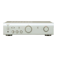
• The photograph is PMA-520AEE2 model.
The viewpoint of each photograph
(Shooting direction)
[View from the top]
Front side
Shooting direction: B
Shooting direction: D
Shooting direction: C
Shooting direction: A
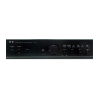
PMA-720AE
FRONT PANEL ASSY
Refer to "DISASSEMBLY
1. FRONT PANEL ASSY"
and "EXPLODED VIEW"
FRONT PCB
(Ref. No. of EXPLODED VIEW : C1)
FUNCTION PCB
(Ref. No. of EXPLODED VIEW : C2)
VOLUME PCB
(Ref. No. of EXPLODED VIEW : C3)
SW/HP PCB
(Ref. No. of EXPLODED VIEW : C4)
ON/OFF PCB
(Ref. No. of EXPLODED VIEW : C5)
MAIN PCB ASSY
Refer to "DISASSEMBLY
3. MAIN PCB ASSY"
and "EXPLODED VIEW"
MAIN PCB ASSY
(Ref. No. of EXPLODED VIEW : C9
POWER TRANSFORMER
Refer to "DISASSEMBLY
4. POWER TRANSFORMER"
and "EXPLODED VIEW"
POWER TRANSFORMER
(Ref. No. of EXPLODED VIEW : C10 )
POWER PCB
Refer to "DISASSEMBLY
2. POWER PCB"
and "EXPLODED VIEW"
POWER PCB
(Ref. No. of EXPLODED VIEW : C6)
CABINET TOP
 Loading...