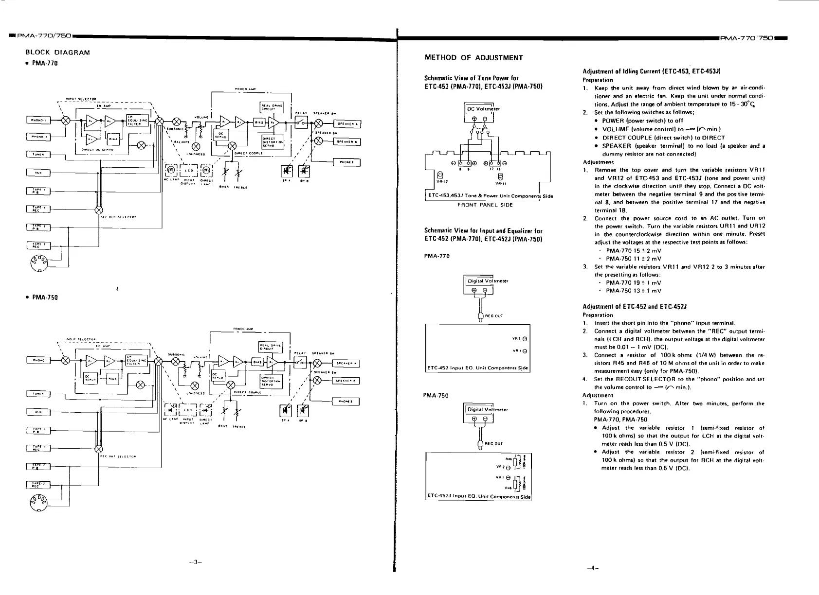
BLOCK
DIAGRAM
PMA-770
METHOD OF ADJUSTMENT
Schematic View of Tone Power for
ETC-453
(PMA-770). ETC-453J (PMA-750)
I
ETC-453.453J Tone
&
Po*..,
Unit
Components
Sida
FRONT
PANEL
SIDE
Schematic View for Input and Equalizer for
ETC-452 (PMA-7701, ETC-452J (PMA-750)
AEC
OUT
T
ETC-452
Input
EO
Unit
Components
Sjde
L
Adjustment
of
Idling Current (ETC-453,. ETC-453J)
Preparation
1.
Keep the unit away from direct wind blown
by
an airandi.
tioner and an electric fan. Keep the unit under normal condi-
tions. Adjust the range of ambient temperature to
15
-
30'~
2.
Set the following switches as follow:
POWER (power switch) to off
VOLUME (volume control) to
--
(r'min.)
DIRECT COUPLE (direct switch) to DIRECT
SPEAKER (speaker terminal) to no load (a speaker and a
dummy
resislor are not connected)
Adjustment
I.
Remove the top cover and turn the variable resistors VRl
l
and VR12 of ETC-453 and ETC-453J (tone and power unit)
in the
clockwire direction until they stop. Connect a DC volt.
meter between the negative terminal 9 and the positive termi-
nal 8, and between the positive terminal
17 and the negative
terminal 18.
2. Connect the power source cord to an AC outlet. Turn on
the power switch. Turn the variable resistors URI
I
and UR12
in the counterclockwise direction within one minute. Preset
adjust the voltages at the respective test points as
follow3:
PMA-770 15
t
2 mV
PMA-750
l
l
?
2 mV
3. Set the variable resistors VRI
1
and VR12 2 to 3 minutes after
the presetting as follows:
PMA-770
I9
+
1
mV
PMA-750 13
t
1
mV
Adjustment of ETC-452 and ETC.452J
Preparation
I.
Insert the short pin into the "phono" input terminal.
2.
Connect a digital voltmeter between the "REC" output
termi.
nals
(LCH and RCHI. the output voltage at the digital voltmeter
mlrst be 0.01
-
1 mV (DC).
3. Connect a resistor of 100 k ohms (114
W)
between the re-
sistors R45 and R46 of
I0 M ohms of the unit in order to make
measurement easy (only for
PMA-750).
4. Set the RECOUT SELECTOR to the "phono" position and set
the volume control to
--a'
(0
min.).
Adjustment
1.
Turn on the power switch. After
two
minutes, perform !he
following procedures.
PMA-770. PMA-750
Adjust the variable resistor 1 Isemi.fixed resistor of
100 k
ohms) so that the output for LCH at the digital volt.
meter reads less than 0.5 V
(DC).
Adjust the variable resistor 2 (semi.fixed resis~ot of
100 k ohms) so that the output for RCH at the digital voll-
meter reads less than 0.5 V (DC).
www.freeservicemanuals.info
 Loading...