EasyManua.ls Logo

Denon POA-6600 Service Manual

Denon POA-6600
33 pages
To Next Page IconTo Next Page
Page #1 background imageLoading...
Page #1 background image

Other manuals for Denon POA-6600

Question and Answer IconNeed help?

Do you have a question about the Denon POA-6600 and is the answer not in the manual?

Denon POA-6600 Specifications

General IconGeneral
BrandDenon
ModelPOA-6600
CategoryAmplifier
LanguageEnglish

Summary

SPECIFICATIONS

COMPONENT IDENTIFICATION

Front Panel Parts

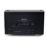
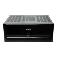
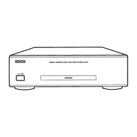
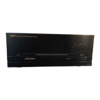
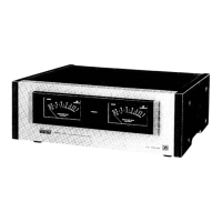
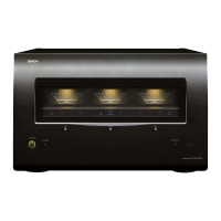
Identification of parts located on the front panel.

Back Panel Parts

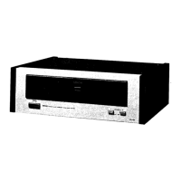
Identification of parts located on the back panel.

CONNECTION PROCEDURES

General Connection Notes

Important advice for proper and safe audio system connections.

Speaker Connection Guide

Detailed instructions for connecting speaker systems to the amplifier.

Line Voltage Selection Guide

Instructions for setting the correct operating voltage for global use.

IMPEDANCE AND CORD HANDLING

Speaker Impedance Requirements

Specifies compatible impedance ranges for connected speakers.

Speaker Cord Connection Methods

Procedures for connecting speaker cords, adapted for different regions.

UNIT DISASSEMBLY

Top Cover Removal Steps

Step-by-step instructions for removing the unit's top cover.

Front Panel Disassembly

Instructions for safely removing the front panel assembly.

Back Panel Disassembly

Procedure for detaching the back panel from the unit.

ADJUSTMENT PROCEDURES

Idle Current Adjustment

Procedure for setting the amplifier's idle current.

Neutral Point Voltage Adjustment

Procedure for adjusting the output stage's neutral point voltage.

Distortion Factor Calibration

Procedure for calibrating the unit for minimum distortion.

TROUBLESHOOTING GUIDE

SYSTEM ARCHITECTURE AND COMPONENTS

Overall System Block Diagram

Schematic representation of the amplifier's functional blocks.

Integrated Circuit (IC) Identification

List and diagrams of integrated circuits used in the amplifier.

SEMICONDUCTOR COMPONENT LIST

Transistor and Diode Identification

Identification and diagrams of transistors and diodes used.

PRINTED CIRCUIT BOARD LAYOUTS

KU9117 Power Unit PCB Layout

Diagram showing the component placement on the KU9117 PCB.

KU9118 POWER SUPPLY UNIT LAYOUT

PARTS LIST - KU9117 POWER UNIT

KU9117 Semiconductor Parts

List of semiconductor components for the KU9117 unit.

KU9117 Resistor Parts

List of resistor components for the KU9117 unit.

PARTS LIST - KU9117 MISCELLANEOUS COMPONENTS

Capacitor, Switch, Coil, Relay Parts

List of capacitor, switch, coil, and relay components.

Other Miscellaneous Parts

List of various other components for the KU9117 unit.

KU9117 PARTS LIST VARIATIONS

Model-Specific Part Differences

Details on part variations for KU9117B and KU9117D models.

PARTS LIST - KU9118 POWER SUPPLY UNIT

WIRING DIAGRAMS

Overall Wiring Diagram

Schematic representation of the amplifier's internal wiring.

WIRING DIAGRAM DETAILS AND CONNECTORS

Connector Pin Assignments

Pin configurations for various internal connectors.

SCHEMATIC DIAGRAMS

KU-9117 Series Schematics

Detailed circuit schematics for the KU-9117 unit.

SCHEMATIC DETAILS AND NOTES

Voltage Measurements and Fuse Information

Key voltage points and fuse specifications within schematics.

SCHEMATIC DIAGRAM GENERAL NOTES

Schematic Diagram Precautions

Important notes regarding schematic interpretation and part changes.

EXPLODED VIEWS AND PARTS LISTS

Chassis and Cabinet Exploded View

Visual breakdown of the unit's physical assembly.

EXPLODED VIEW PARTS LIST

Component Parts List

List of components referenced in the exploded view.

ASSEMBLY HARDWARE

Screws and Nuts List

List of screws and nuts used for assembly and mounting.

ADDENDUM LIST

SAFETY WARNINGS AND PRECAUTIONS

Component Safety Requirements

Mandatory safety requirements for replacement parts.

Leakage Current Testing Procedure

Procedure for testing and ensuring safety leakage current limits.

Related product manuals