The provided document is a service manual for the Denon POA-T2/T3 and POA-3200 Stereo Power Amplifiers, which are Hi-Fi components.
Function Description
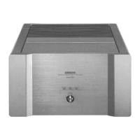
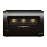
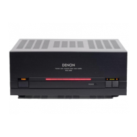
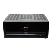
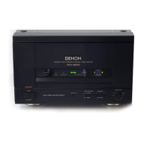
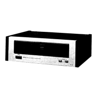
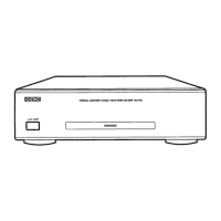
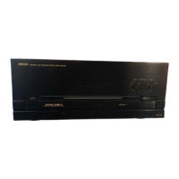
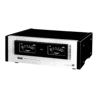
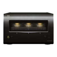
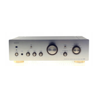
The Denon POA-T2/T3 and POA-3200 are stereo power amplifiers designed to deliver high-fidelity audio output. These amplifiers are part of a Hi-Fi component system, intended to be connected to a pre-amplifier for signal input and to speaker systems for audio output. They feature multiple channels, with the POA-T3 model specifically supporting a center channel in addition to left and right, making it suitable for multi-channel audio setups. The amplifiers are equipped with protection circuits to ensure stable and safe operation, and they include a motor fan for heat dispersion. Remote control functionality is also supported when connected to a compatible Denon pre-amplifier.
Important Technical Specifications
The technical specifications provided in the manual detail the performance characteristics of the POA-T2 and POA-T3 models.
Power Amplifier Section:
- Rated Output Power (8 Ω/ohms Load):
- 20 Hz to 20 kHz, T.H.D. 0.02%: 120 W
- DIN, 1 kHz, T.H.D. 0.5%: 200 W
- Rated Output Power (4 Ω/ohms Load):
- DIN, 1 kHz, T.H.D. 0.5%: 200 W
- Total Harmonic Distortion (-3 dB at rated output, 8 Ω/ohms) (1 kHz): 0.008%
- Intermodulation Distortion (60 Hz/7 kHz: 4/1 at rated output, 8 Ω/ohms): 0.002%
- Power Band Width (8 Ω/ohms, T.H.D. 0.05%): 5 Hz – 50 kHz
- Frequency Response (+0, -3 dB at 1 W): 1 Hz – 100 kHz
- Input Sensitivity (Normal in): 1.1 V
- Input Impedance (Normal in): 47 kΩ/kohms
- Output Impedance (1 kHz): 0.1 Ω/ohms
- S/N Ratio (IHF, A-weighting) (Normal): 110 dB
Output Terminals:
- Speakers:
- A or B: 4 Ω/ohms ~ 16 Ω/ohms
- A + B: 8 Ω/ohms ~ 16 Ω/ohms
General:
- Power Supply: AC 230 V/50 Hz
- Power Consumption:
- POA-T3: 470 W
- POA-T2: 330 W
- Dimensions (Including control knobs and feet): 434 (W) x 135 (H) x 353 (D) mm (17-3/32" x 5-11/32" x 13-29/32")
- Weight:
- POA-T3: 16 kg (35 lbs 4 oz)
- POA-T2: 12.3 kg (27 lbs 2 oz)
Usage Features
The amplifiers offer several features for user interaction and system integration:
- Power Switch (POWER): A push-button switch to turn the unit on and off. Upon power-on, the POWER indicator flashes for a few seconds before lighting steadily, indicating stable operation.
- Power Indicator: Lights orange when the power is on and turns red when the power is turned off via the remote terminal.
- Speaker Selector Buttons (SPEAKERS): Buttons A and B allow users to select which speaker systems (A, B, or both) are active. Setting both to "OFF" mutes the speaker output, useful for headphone listening.
- Speaker System Terminals: Connects to speaker systems. Proper polarity (+ to + and - to -) is crucial for optimal sound quality.
- Remote Terminal (REMOTE ON-OFF): This terminal enables remote control of the amplifier's power when connected to a compatible Denon pre-amplifier. A low-voltage DC current is emitted to turn on the pre-amplifier, and the main unit's power can be controlled via the pre-amplifier's remote control unit. It also allows for turning on/off other power amplifiers connected in a multi-amp setup.
- AC IN: Connects the unit to a power outlet using the provided AC power cord.
- Input Terminal (INPUT): RCA connectors for connecting to the pre-amplifier's pre-out terminal.
- Protector Circuits: The unit includes various protection circuits that interrupt output in cases such as muting time after power-on, offset voltage drift, abnormally high temperature, or shorted/low impedance speaker terminals.
- Heat-Dispersing Motor Fan: Activates automatically when the internal temperature rises to disperse heat, ensuring stable operation.
Connection Guidelines:
- Always ensure all connections are complete before plugging in the power cord.
- Connect left (L), center (C, for POA-T3), and right (R) channels correctly.
- Securely insert all plugs to prevent noise.
- Avoid bundling pin-plug cords with the power cord or placing them near the power transformer to prevent hum or noise.
- Speaker Impedance: For single A or B terminal use, speakers should have a nominal impedance of 4 to 16 Ω/ohms. For A+B simultaneous use, speakers must have an impedance of 8 to 16 Ω/ohms to prevent malfunction. Lower impedances may trigger the protective circuitry.
Maintenance Features
The manual provides instructions for basic troubleshooting and adjustment, but emphasizes that servicing should be performed by qualified personnel.
Troubleshooting:
A flow chart guides users through common issues like "No sound." It prompts checks for:
- Correct connections (speaker cords, input jacks, remote plug cord).
- Power indicator status (orange for ON, red for remote OFF).
- Power supply cord connection.
- Pre-amplifier functionality.
If these checks don't resolve the issue, it suggests a power supply circuit or power amplifier malfunction, requiring professional service.
Method of Adjustment:
Two main adjustments are detailed:
-
Idle Current Adjustment:
- Setup: Place the unit in a normal ambient temperature (15-30°C), away from direct airflow. Set the power switch to OFF, speaker terminals to no load (speakers disconnected, but SP-A switch ON), and disconnect the input terminal.
- Adjustment: Connect a DC Voltmeter to Test points (TP101) of the 1U-2909 board. Turn the POWER switch ON. Adjust VR102 to read 2 ± 0.5mV. After a 3-minute warm-up, readjust VR102 to 2 ± 1mV. Repeat for each channel.
-
Offset Adjustment:
- Setup: Same environmental conditions as idle current adjustment. Set the power switch to OFF, speaker terminals to no load (speakers disconnected, but SP-A switch ON), and disconnect the input terminal.
- Adjustment: Connect a Speaker A terminal to a DC Voltmeter and oscilloscope (set to 5mV/div). Turn the POWER switch ON. Adjust VR101 to read 0 ± 1mV. After a 3-minute warm-up, readjust VR101 to 0 ± 1mV. Repeat for each channel.
Disassembly Instructions:
Detailed steps are provided for disassembling the unit, including:
- Top Cover: Remove 8 screws (A) and 2 screws (B) to detach the top cover.
- Front Panel: Remove 4 upper screws (D) and 2 screws (C) to detach the front panel.
- Each P.W.Board of Front Panel: Instructions for detaching the Speaker Switch P.W.Board, Power Supply Switch P.W.Board, and LED P.W.Board by removing screws (E, F) and undoing hooks.
- Each P.W.Board and Fan of Rear Panel: Steps for removing the Protector P.W.Board, Preset P.W.Board, Input (R, C, L) P.W.Board, and Fan Cover by removing screws (G, H, I, J) and undoing holders.
- Power Supply Transformer: Remove 12 screws (K) to detach the 3 (POA-T3) or 2 (POA-T2/3200) power supply transformers.
- Power Amp. P.W.Board: Undo 2 holders, remove a screw (L), and 4 screws (M) to detach the 3 (POA-T3) or 2 (POA-T2/3200) Power Amp. P.W.Boards.
Safety Warnings:
The manual includes critical safety warnings, such as "RISK OF ELECTRIC SHOCK, DO NOT OPEN." It advises against removing covers, as there are no user-serviceable parts inside, and refers servicing to qualified personnel. It also warns against exposure to rain or moisture to reduce fire or electric shock risk. Parts marked with a triangle symbol (A) have critical characteristics, and only manufacturer-recommended replacement parts should be used.