Do you have a question about the Denon PRA-S10 and is the answer not in the manual?
Covers operating instructions, warnings, and general safety adherence for appliance usage.
Details risks of electric shock, user serviceability, and when to seek qualified service personnel.
Advises against water exposure, proper ventilation, heat sources, and object/liquid entry.
Provides specific cautions for U.S.A. & Canada and European models regarding plugs and installation.
Specifies minimum clearance needed between the unit and other components for adequate ventilation.
Details how to connect various audio components like CD players, tuners, and tape decks.
Offers advice on avoiding high temperatures, protecting the power cord, and keeping the unit dry.
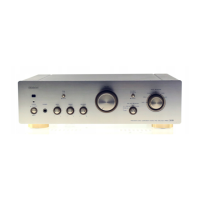
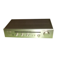
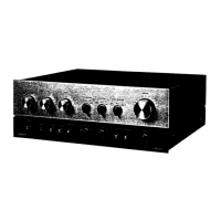
Explains the functions of Power, Phones, Bass, Treble, Volume, Input Selector, and Rec Out Selector.
Details input/output terminals, CD input switches, Phono selector, and remote control sensor.
Instructions for setting the correct line voltage for the unit based on region.
Covers initial setup, playing records, CDs, radio, tape decks, and tape copying procedures.
Provides instructions for inserting and replacing batteries in the remote control unit.
Offers tips on operating the remote control effectively and avoiding common operational issues.
Explains the functions of Power, Muting, and other dedicated buttons on the RC-185 remote.
Details power requirements, consumption, dimensions, weight, and remote control system specifications.
Details the process for removing the Top Cover, Front Panel, and Rear Panel components.
Instructions for adjusting the output offset voltage for both left and right channels using voltmeters.
Details part numbers, names, and remarks for transistors, ICs, and diodes on the PWB.
Lists part numbers, values, and specifications for resistors and capacitors on the PWB.
Lists components specific to the Control Unit, including variable resistors and capacitors.
Lists miscellaneous parts like fuses, relays, connectors, and packing materials.
Illustrates the physical arrangement of components and traces on the Pre Amp Unit's circuit board.
Visual representation of the Control Unit's Printed Wiring Board, detailing component placement.
Lists parts for the main unit, including chassis, boards, and functional modules.
Details items included in the packaging, such as manuals, cords, and accessories.
Detailed pinout and function descriptions for various ICs used in the pre-amplifier.
Information on transistors, diodes, and LEDs, including their types, functions, and diagrams.
| Type | Preamplifier |
|---|---|
| Number of Channels | 2 |
| Total Harmonic Distortion (THD) | 0.002% |
| Signal-to-Noise Ratio | 110 dB |
| Output Level | 1 V |
| Dimensions (W x H x D) | 434 x 95 x 338 mm |
| Input Impedance | 47 kOhms |
| Output | 1 V |
| Input Sensitivity | 200 mV (Line) |