EasyManua.ls Logo

Denon POA-F100 Service Manual

Denon POA-F100
16 pages
To Next Page IconTo Next Page
Page #1 background imageLoading...
Page #1 background image
DENON
SERVICE
MANUAL
MODEL
POA-F100
3
CHANNEL
POWER
AMPLIFIER
Hi-Fi
Component
PERSONAL
COMPONENT
SYSTEM
/
TRIPLE
POWER
AMPLIFIER
POA-F100
—TABLE
OF
CONTENTS
SAFELY
PRECAUTIONS
ijcs5cicsstusbccatcescenssenscuicecdanseivacdustcesaneandoacs
baeectauusueds
aps
veneasvoueradrensunevansuadaSubsncnuaseeees
2
SPEGIFIGA
TIONS
ccacesssseisvaceancatesusanepacsen
tees
canedaeiensaseinevet
as
oacuateuinsdan
deste
ts
ausasaatnoeguecannauroussiasaenanatanes
tasanuaeees
2
DISASSEMBLY
siicieicshs
is
ested
esacs
capsid
cs
ehrtces
ereesnset
eancaatnaeacveaevatdnneioums
sudegeusnensueSerenatanaeatie
cede
uneveoeonns
3,4
PID
MIST
IMENT
scesceusace
see
coccas
pana
cecemuaaseapucased
vecen
cee
cnssaupseewsdccensearayavcner
eum
caeendceuetenabes
evap
evant
eeabi
de
goeetortueentans
5
BLOCK:
DIAGRAM
sicsccccgtctevoti
ca
tecsecas
Se
ccheusustuceceaestb
dae
etetiin
de
edveiuc
bad
tend
snaausias
uagpensdauedapestvestasouetanennensean@eeersn
6
BEVEL
DIAGRAM
sess
setecatecsccat
pic
htiascatenncils
Zeusds
cameesiockunicaypescatinesapataseyapansain
mcwes
cieongnatunipan
ces
esaatonaaanessnceeeeedeeeaenes
7
SEMIGONDUG
[ORG
-siiiveaseacrrvcateperticetccavciiamanieeseenedtnes
teongensetunssunewsumeuunauaeanncanseueeneducevernelveassusestusvieeadbicnniiiens
8
PRINTED
WIRING
BOARDS
wiviscecececezsnccietiapeanweaerecercnceaincecanddacnnstatsadeosoashevavenasssoasesnatnasniveaciauneeassnbnnciiewnncerss
9
NOTE-FOR
PAR
Te
EUS
Misxsscsctsctssecescscnanaidecinas
Saha
atsenecenaaroncaecs
cancucdieteaateedontannaes
ileeatheateusneacnanusdteeeceseatentiys
10
PARTS.LIST
OF
P.W.B.
UNIT
ASS
EY
vriiccncecsh
owes
sncishenavaecccastennsnsesueunsueesunenapsceassetisneraaleaaeaseanareesen
oossendee
10,11
EXPIEODED
VE
WW
sec
stericscosinaewonesss
ceauseeioecee
sales
guise
teiays
Gace
readied
ta
tdancic
casa
sehawtsntaais
seteeudene
sauce
sawbnancaaepees
cu
siauige
12
PARTS:
LIST
OF
EXPLODED:
VIEW
sssisssiicencthccsecctewcaciastbcancecaataoneuancagectececetin
dadvoncsedeecseeiassietaceaasseMeosoaueceens
13
PACKING:
VIEW
siisic
doses
den
Saatticsses
ae
ticanue
cussetievaxseenededietse
ue
cnuscucrte
cpa
cvs
oncbbocuduauetavpestauel
ou
cdesneh
suatseuusnanuewonsenneress
14
PARTS
LIST
OF
PACKING
&
ACCESSORIES
.............essssessssscsecesecceeersssenesssnsenssscsceascuenspessnasseeea
Haasenereease
14
WIFRING
DIAGN
wice
coisas
cctecoctacoarts
ee
dsseti
chaos
chan
toan
sete
nencde
ts
caieateta
sea
ce
eacees
ea
aeaniuutse
Mone
snaguguannnbewseuddasamsdeeeesceies
15
SCHEMATIC
DIAGRAM
sicsssenssocrssieolatectonsacett
ate
whaceotncecaes
aac
ctacebcee
nskeaedsacencudaupentese
ei
aeen
seued
ueuatanaatures
dete
santhtuiavars
16
NIPPON
COLUMBIA
CO.
LTD.
X0096
Question and Answer IconNeed help?

Do you have a question about the Denon POA-F100 and is the answer not in the manual?

Denon POA-F100 Specifications

General IconGeneral
TypePower Amplifier
Channels2
Input Sensitivity1.2 V
Input Impedance47 kohms
Signal to noise ratio100 dB
Speaker load impedance4 - 16 ohms
Dimensions434 x 150 x 375 mm (W x H x D)
Weight8.5 kg
Frequency Response10 Hz - 100 kHz

Summary

Denon POA-F100 Service Manual Overview

Safety Precautions

Essential safety checks and warnings for service technicians and customers.

Specifications

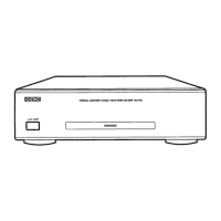
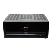
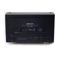
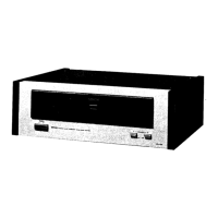
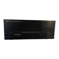
Detailed technical specifications of the Denon POA-F100 amplifier.

Disassembly Procedures

Top Cover and Front Panel Removal

Steps for removing the top cover and front panel assembly.

Front P.W.B. Detachment

Procedure to detach the Front P.W.B. from the front panel.

Back Chassis and AMP P.W.B. Removal

Steps to detach the back chassis, AMP P.W.B., and Main Heat Sink.

Main P.W.B. Detachment

Steps to detach the Main P.W.B.

Adjustment Procedures

Idling Current Adjustment

Procedure for adjusting the idling current using a DC voltmeter.

Diagrams and Component Identification

Block Diagrams

Functional block diagrams illustrating the amplifier's circuitry.

Level Diagram

Diagram showing signal levels and gains through amplifier stages.

Semiconductors

Identification and types of ICs, transistors, and diodes used.

Printed Wiring Board and Parts List

Printed Wiring Board Layout

Diagram showing the layout of components on the printed wiring board.

Note for Parts List

Important notes regarding parts ordering, availability, and specifications.

Main P.W.B. Unit Components

Component list for Semiconductors, Resistors, and Capacitors on the main P.W.B.

Other Parts Group

List of miscellaneous parts like connectors, fuses, and speaker terminals.

Exploded and Packing Views

Exploded View

Diagram showing the assembly of all unit parts with reference numbers.

Parts List of Exploded View

Detailed list of parts corresponding to the exploded view.

Packing View

Diagram illustrating the packaging of the unit and accessories.

Parts List of Packing & Accessories

List of items included in the product packaging.

Wiring and Schematic Diagrams

Wiring Diagram

Diagram showing electrical connections between internal components.

Schematic Diagram

Detailed circuit schematic of the amplifier.

Related product manuals