Do you have a question about the Denon TU-660 and is the answer not in the manual?
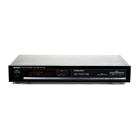
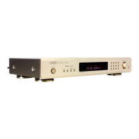
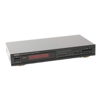
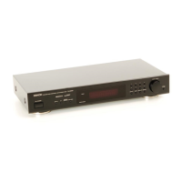
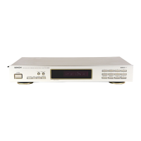
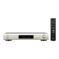
Identifies the specific model series of the stereo tuner.
Outlines the main sections covered in the service manual.
Essential guidelines for safe operation and handling of the appliance.
Specific warnings about electric shock hazards and proper usage.
Guidance on optimal placement and environmental conditions.
Precautions related to grounding and polarization.
Details on connecting FM and AM antennas, including adapter usage.
How to connect the tuner's output to other audio equipment.
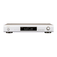
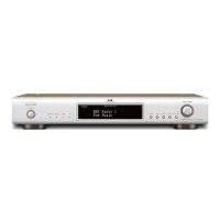
Identification and function of buttons, lights, and displays on the front panel.
Important notes and warnings during tuner operation.
Explanation of power, signal, stereo, and MPX NR indicators.
Controls for tuning modes, IF band, and band selection.
Buttons and indicators related to station memory and preset recall.
Detailed technical data for the FM reception band.
Detailed technical data for the AM Medium Wave reception band.
Overall technical details like power supply and dimensions.
Guidance on connecting the mains lead colors for UK models.
Instruction to record the unit's serial number for future reference.
Instructions for setting the line voltage on multi-voltage models.
How to configure the tuning frequency step size.
Detailed steps for connecting FM antennas, including coaxial and 300-ohm types.
Instructions for connecting and positioning the AM loop antenna.
Functions for tuning mode selection and IF band adjustments.
Explanations of memory, signal strength, and channel indicators.
How the digital frequency indicator displays reception frequencies.
Steps for checking connections, antenna, and operational warnings.
Important notes and tips for using the tuner effectively.
A summary of the tuner's technical specifications.
How to insert batteries and important usage notes for the remote.
Instructions on operating the tuner using the remote control unit.
Visual representation of the tuner's internal circuitry and signal flow.
Step-by-step guide to remove the tuner's top cover and front panel.
Procedures for removing various circuit boards and front panel components.
Diagrams showing how to connect test equipment for adjustments.
Locations on the circuit boards for making FM and AM adjustments.
Detailed steps for aligning the FM frontend section.
Detailed steps for aligning the AM Medium Wave and Long Wave frontend.
List and pinouts of integrated circuits used in the tuner.
Identification of transistors, diodes, and LEDs with their types.
Important information regarding part availability and ordering.
Component list for the 2-band European tuner unit.
Component list for the US/Canada 2-band tuner unit.
Component list for the Asian 2-band tuner unit.
Component list for the 3-band European tuner unit.
Component list for the UK tuner unit.
Shows the component layout on the 2-band model's circuit board.
Shows the component layout on the 3-band model's circuit board.
Detailed component layout for the 3-band model's circuit board.
Illustrated breakdown of all physical parts of the tuner.
Detailed parts for the 2-band model's exploded view.
Supplementary list of parts not covered in the main exploded view.
Diagram showing internal wire routing and connections between units.
Detailed electronic schematic for the 2-band tuner model.
Detailed electronic schematic for the 3-band tuner model.
| Tuning Bands | FM, MW |
|---|---|
| Signal to Noise Ratio (FM) | 70 dB |
| Signal to Noise Ratio (MW) | 50 dB |
| Frequency Response (FM) | 30 Hz - 15 kHz |
| Tuning Scale | Analog |
| FM Tuning Range | 87.5 - 108.0 MHz |
| MW Tuning Range | 522 - 1611 kHz |
| Distortion (FM) | 0.3% |
| Distortion (MW) | 0.5% |
| Power Supply | AC 230V |
| Type | Stereo Tuner |
| Sensitivity (FM) | 1.0 µV |