www.desatech.com
113900-01D 9
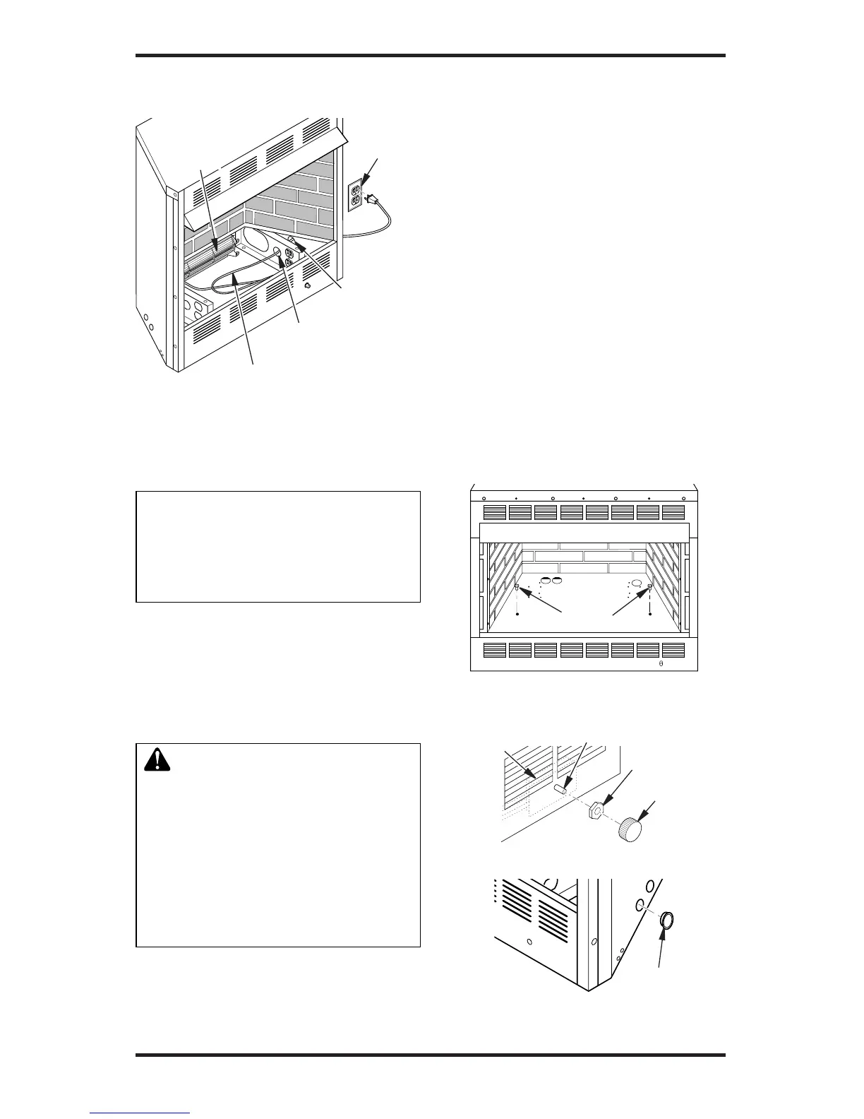
Side
Opening
Support Bracket
Opening
Blower Power
Cord
Figure 8 - Routing Blower Power Cord
for Conventional Installation
Electrical
Outlet
Blower
INSTALLING BLOWER SPEED
CONTROL
Notice: If a log set is currently in-
stalled in the rebox, disconnect
log set from gas supply and remove
from rebox. Contact a qualied
service person to do this.
Note:Appearanceofreboxmayvaryslightly
depending on model.
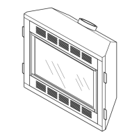
1. Removethereboxbottom:
a. Remove the 2 screws that secure the
bottomoftherebox(seeFigure9,).
b. Carefullyraiseandremovetherebox
bottomfromtherebox.
WARNING: If there is a du-
plex electrical outlet installed in
the right side of the bottom of
the replace base area, be sure
that the electrical power to the
outlet is turned off before pro-
ceeding with blower installation.
Failure to do this may result in
serious injury.
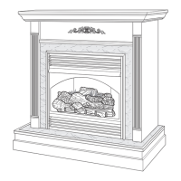
2. Remove shipping screw from speed
control in right support leg. Place speed
control against inner wall of front panel,
pushing the plastic control shaft forward
through the opening (see Figure 10).
INSTALLATION
Continued
3. While supporting speed control, secure
control shaft with lock nut by pushing and
turning lock nut with pliers clockwise until
it is tight against front panel. Place control
knob provided on shaft (see Figure 10).
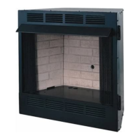
4. Plug in blower power cord.
a. If your rebox is installed as a free-
standing unit, determine whether the
power cord will exit the left side or the
rightsideoftherebox.Install1plastic
bushing provided into the 1
1
/
2
" hole in
theoorsupportontheexitside.Install
the second plastic bushing provided
into the 1
1
/
2
" hole in the outer casing
through which the power cord will exit
(see Figure 11). Route power cord
through both plastic bushings and plug
the power cord into a 3-prong grounded
wallreceptacleneartherebox.
b. If your firebox installation is re-
cessed and/or pre-wired, plug the
power cord into the duplex outlet
provided.
Figure 10 - Attaching Speed Control
Figure 9 - Removing Screws from
Firebox Bottom
Screws
Control Shaft
Speed
Control
Lock Nut
Control
Knob
Figure 11 - Installing Plastic Bushing for
Power Cord
Plastic Bushing