www.desatech.com
119303-01E
12
BUILT-IN FIREBOX INSTALLATION
Built-in installation of this rebox involves
installing rebox into a framed-in enclosure.
This makes the front of rebox ush with wall.
Optional brass trim accessories are available
(see Accessories, page 27). The brass trim
will extend past sides of rebox approximately
1/2". This will cover the rough edges of the
wall opening. If installing a mantel above the
rebox, you must follow the clearances shown
in Figure 8, page 10. Use the following instruc-
tions to install the rebox in this manner.
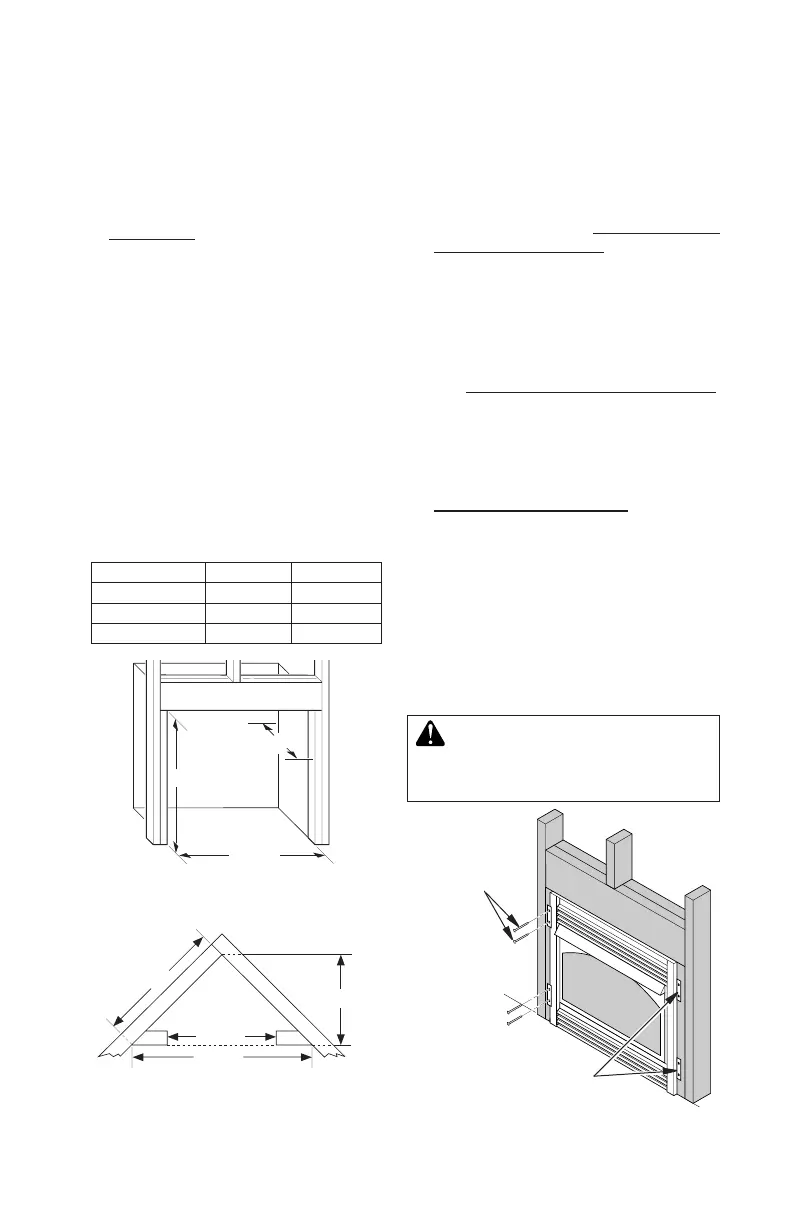
1. Frame in rough opening. Use dimensions
shown in Figure 13 for the rough opening.
If installing in a corner, use dimensions
shown in Figure 14 for the rough opening.
The height is 33" which is the same as the
wall opening above.
2. If using blower, install and properly ground
GA3555, three-prong 120 volt electrical
outlet, in replace. Follow instructions
included in kit.
INSTALLATION
Continued
Figure 13 - Rough Opening for Installing
in Wall
Figure 14 - Rough Opening for Installing
in Corner
39
3
/8
"
27
7
/8
"
55
5
/8
"
35
1
/2
"
Figure 15 - Attaching Fireplace to Wall
Studs
Nailing
Flanges
Nails or Wood
Screws
3. Install gas piping into replace location.
This installation includes an approved
exible gas line (if allowed by local codes)
after the equipment shutoff valve. The ex-
ible gas line must be the last item installed
on the gas piping. See Installing Gas Pip-
ing to Fireplace Location, page 13.
4. Carefully set replace in front of rough
opening with back of replace inside wall
opening.
5. Carefully insert fireplace into rough
opening.
6. Attach exible gas line to gas supply.
See Connecting Fireplace to Gas Supply,
page 15.
7. Attach replace to wall studs using nails
or wood screws through holes in nailing
ange (see Figure 15).
8. Check all gas connections for leaks. See
Checking Gas Connections, page 16.
9. Plug electrical cord into electrical outlet
installed in step 2.
10. Install trim after nal nishing and/or paint-
ing of wall (see Figure 7, page 10).
IMPORTANT: When nishing your rebox,
combustible materials such as wall board,
gypsum board, sheet rock, drywall, plywood,
etc. may be butted up next to the sides and top
of the rebox. Combustible materials should
never overlap the rebox front facing.
WARNING: Do not allow any
Actual Framing
Height 32 3/8" 33"
Front Width 34
5
/
16
" 35
1
/
2
"
Depth 16
11
/
16
" 17
3
/
4
"