www.desatech.com
119303-01E
15
INSTALLATION
Continued
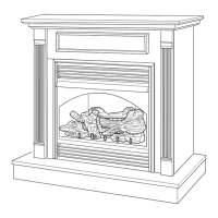
Figure 19 - Removing Log Base
Assembly From Fireplace
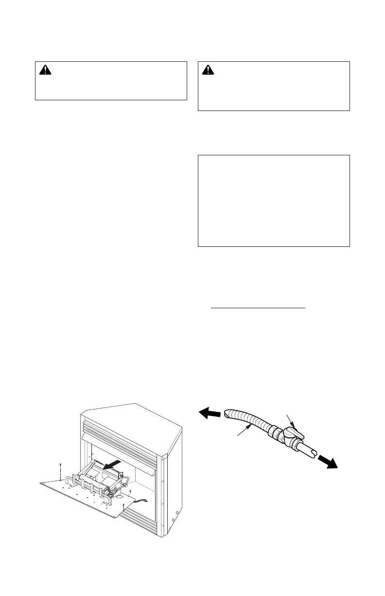
Figure 20 - Attaching Flexible Gas Lines
Flexible Gas Line
from Fireplace
Gas Regulator
To Fireplace
Gas Regulator
Equipment
Shutoff Valve
Provided by
Installer
To External
Regulator
Natural Gas
To Gas Meter
3. Route gas line (provided by installer)
from equipment shutoff valve to replace.
Route exible gas supply line through one
of the access holes.
-
4. Attach the exible gas line to gas supply
(see Figure 20). Check tightness of ex-
ible gas line attached to gas regulator of
replace (see Figure 20).
5. Check all gas connections for leaks. See
Checking Gas Connections, page 16.
6. Replace log base assembly back into
replace. Feed exible gas line into re-
place base area while replacing log base
assembly. Make sure the entire exible
gas line is in replace base area. Reat-
tach log base assembly to replace with
screws removed in step 2.
We recommend that you install a sediment
trap in supply line as shown in Figure 18.
Locate sediment trap where it is within reach
for cleaning. Install in piping system between
fuel supply and replace. Locate sediment
trap where trapped matter is not likely to
freeze. A sediment trap traps moisture and
contaminants. This keeps them from going
into replace gas controls. If sediment trap
is not installed or is installed wrong, replace
may not run properly.
Installation Items Needed
• 5/16" hex socket wrench or nut-driver
• Phillips screwdriver
• sealant (resistant to propane/LP gas, not
provided)
1. Remove replace screen. Remove one
screw that holds replace screen in place
for shipping. This screw is located near top
left side of screen. Discard screw. Lift re-
place screen up and pull out to remove.
2. Remove screws that attach log base
assembly to replace (see Figure 19).
Carefully lift up log base assembly and
remove from replace (see Figure 19).
Note: If adding the G8000 series brick liner
accessory, install it now. Follow instructions
in G8000 accessory kit.