PREFACE LAC/LFC Series Oven Owner’s Manual
6 Version 1.12
Copyright © 2018 by Despatch Industries.
All rights reserved. No part of the contents of this manual may be reproduced, copied or transmitted in any form or by any
means including graphic, electronic, or mechanical methods or photocopying, recording, or information storage and
retrieval systems without the written permission of Despatch Industries, unless for purchaser's personal use.
Figure 3. Locate the forced exhaust airflow switch on the back of the oven. ............................... 21
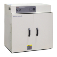
Figure 4. LAC High-performance Bench-top Oven. ..................................................................... 22
Figure 5. Horizontal Airflow through the LAC Oven. .................................................................. 22
Figure 6. Damper Positions. .......................................................................................................... 25
Figure 7. LFC Oven Exhaust Damper Control. ............................................................................. 25
Figure 8. Protocol 3 Controller Operator Interface. ...................................................................... 27
Figure 9. LAC2-18-8 Nameplate. .................................................................................................. 31
Figure 10. Rear Access Panel for Hard-Wired Connections. ........................................................ 32
Figure 11. Control panel removal. ................................................................................................. 32
Figure 12. Power Connections at Main Circuit Board. ................................................................. 33
Figure 13. Circuit Board. ............................................................................................................... 39
Figure 14. Test Recirculation and Exhaust Airflow Switches. ...................................................... 42
Figure 15. Oven Control Circuit Board LEDs indicate status of switches. ................................... 43
Figure 16: Shipping anchors Figure 17: Wall separator/anchor ............................................... 45
Figure 18: Latch Adjustment Figure 19: Spring removal ...................................................... 45
Figure 20. Remove Screws to Remove Ceiling Plate. ................................................................... 47
Figure 21. Heater Panel and Inlet Cone. ........................................................................................ 47
Figure 22. Remove Heater Panel by Removing Screw in Front Edge of Each Panel. .................. 48
Tables
Table 1. Operating/Environmental Conditions (For indoor use). .................................................. 15
Table 2. Troubleshooting Oven Symptoms. .................................................................................. 49
Table 3. Troubleshooting with Control Panel Mounted Circuit Board. ........................................ 50
Table 4. Error Messages and Next Steps. ...................................................................................... 51
Table 5. MRC 5000 Settings. ........................................................................................................ 53