2
95-87513.1
NOTE
The PC must always be located in a non-
hazardous controlled location.
Modbus communications are only available on X-series
detectors that have Relay, Relay/4-20mA, and Pulse
outputs. Modbus communications are not available on
X-series detectors that have HART or EQP outputs.
NOTE
Communication between the sensor module and
the PC uses the Modbus RTU protocol, with the
sensor module congured as a Modbus slave.
Alternate Method
NOTE
The alternate method must be used with EQP
and HART models since these detectors are not
furnished with RS-485 output terminals.
This method requires removal of the sensor module from
the detector housing for testing in a control room. A 5/64
inch Allen wrench is needed to loosen the lock screw
when removing the module.
To remove the sensor module follow these steps:
1. Remove power from the detector.
2. Using the allen wrench supplied with the detector,
loosen the locking screw on the side of the housing.
3. Unscrew the sensor module and remove it from the
front of the detector housing.
WARNING
Do not open the detector assembly in a hazardous
area when power is applied.
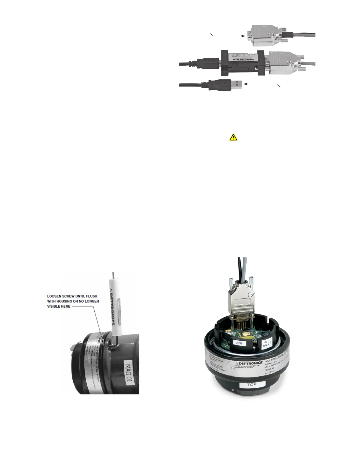
Connector includes a power supply that can plug into
any standard 120/240 vac outlet.
The Inspector Connector utilizes an integral RS-485
to USB converter (see Figure 2) to ensure proper
communication.
Connect the converter end of the Inspector Connector to
the USB port of the PC. Connect the end with the power
supply connection to the sensor module (see
Figure3).
CONNECT THIS END OF
INSPECTOR CONNECTOR
TO THE PC USB PORT.
CONNECT THIS END TO
THE SENSOR MODULE.
A2485
Figure1— Removing the Sensor Module
Figure2—Inspector Connector with RS-485 to USB Converter
Figure3—Connecting Inspector Connector to sensor module
 Loading...


