Model DM-700
DM-700 Instruction Manual Rev. 5.1 Page 2 of 51
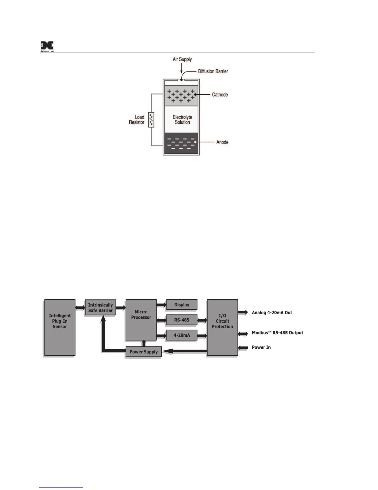
Figure 2 Construction of Galvanic Cell
1.2 Sensor Electronics Design
Intelligent Transmitter Module
The DM-700 Intelligent Transmitter Module (ITM) is a fully encapsulated microprocessor-based package that
is universal in design and will accept any Detcon intelligent plug-in electrochemical gas sensor. The ITM design
uses an internal intrinsically safe barrier circuit that lifts the requirement for use of flame arrestors to achieve
Class 1, Division 1 (Zone1) area classification. This facilitates fast response times and improved calibration
repeatability on highly corrosive gas types. The ITM circuit functions include extensive I/O circuit protection,
on-board power supplies, internal intrinsically safe barrier circuit, microprocessor, LED display, magnetic
programming switches, a linear 4-20mA DC output, and a Modbus™ RS-485 output. Magnetic program
switches located on either side of the LED Display are activated via a hand-held magnetic programming tool,
thus allowing non-intrusive operator interface with the ITM. Calibration can be accomplished without
declassifying the area. Electrical classifications are Class I, Division 1, Groups A B C D, Class I, Zone 1, Group
IIC, and II 2G Ex d ib IIC Gb (sensor only).
Figure 3 ITM Circuit Functional Block Diagram