Model FP-524D
FP-524D Instruction Manual Rev. 1.6 Page 9 of 39
2.6 Field Wiring
Detcon Model FP-524D combustible gas sensor assemblies require three conductor connections between
power supplies and host electronic controller’s 4-20mA output. A 250 ohm load resistor is needed on the 4-20
mA line when it is not being used. Wiring designations are DC+, DC-, and MA (sensor signal). The
maximum wire length between sensor and 24VDC source is shown in the Table below. The maximum wire
size for termination in the Junction Box is 14 AWG.
Table 1 Wire Gauge vs. Distance
AWG Wire Dia. Meters Feet
NOTE 1: Wiring table is based on stranded tinned copper wire and is designed to serve as a
reference only.
NOTE 2: Shielded cable is required for installations where cable trays or conduit runs include
high voltage lines or other possible sources of induced interference. Separate conduit runs are
highly recommended in these cases.
NOTE 3: The supply of power should be from an isolated source with over-current protection
as stipulated in table.
NOTE 4: A 250 ohm load resistor is needed on the 4-20 mA line when it is not being used.
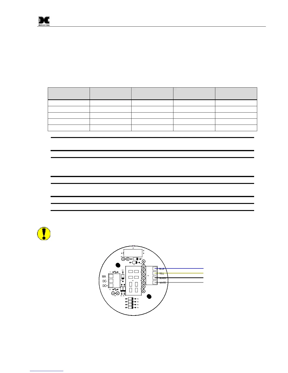
Terminal Connections
CAUTION: Do not apply system power to the sensor until all wiring is properly terminated. Refer to
Section 2.8 Initial Start Up.
Customer
Wiring
White
Blue
Yellow
Black
Wiring to
LEL Sensor
Figure 11 Sensor Connector PCB
a) Remove the junction box cover and unplug the Transmitter Module. Identify the terminal blocks for
customer wire connections.