Model FP-524D
FP-524D Instruction Manual Rev. 1.6 Page 10 of 39
b) Observing correct polarity, terminate the 3-conductor 4-20mA field wiring (DC+, DC-, and MA) to the
sensor assembly wiring in accordance with the detail shown in Figure 11.
c) Trim all exposed wire leads if they are not permanently landed in the terminal block.
d) Plug the Transmitter Module into the connector PCB and replace the junction box cover.
NOTE: A 6-32 or 8-32 threaded exterior ground point is provided on most junction boxes for
an external ground. If the Sensor Assembly is not mechanically grounded, an external ground
strap must be used to ensure that the sensor is electrically grounded.
2.7 Remote Mounting Installation
Some sensor mounting applications require that the gas sensor head be remotely mounted away from the
sensor transmitter. This is usually true in instances where the gas sensor head must be mounted in a location
that is difficult to access. Such a location creates problems for maintenance and calibration activities. Detcon
provides the FP-524D sensor in a remote-mount configuration in which the sensor (Model FP-524D-RS) and
the transmitter (Model FP-524D-RT) are provided in their own condulet housing and are interfaced together
with a three conductor cable. There is a limit 0.5 ohm maximum resistance drop per wire over the separation
distance.
AWG Maximum Separation (feet)
20 50
18 75
16 125
14 175
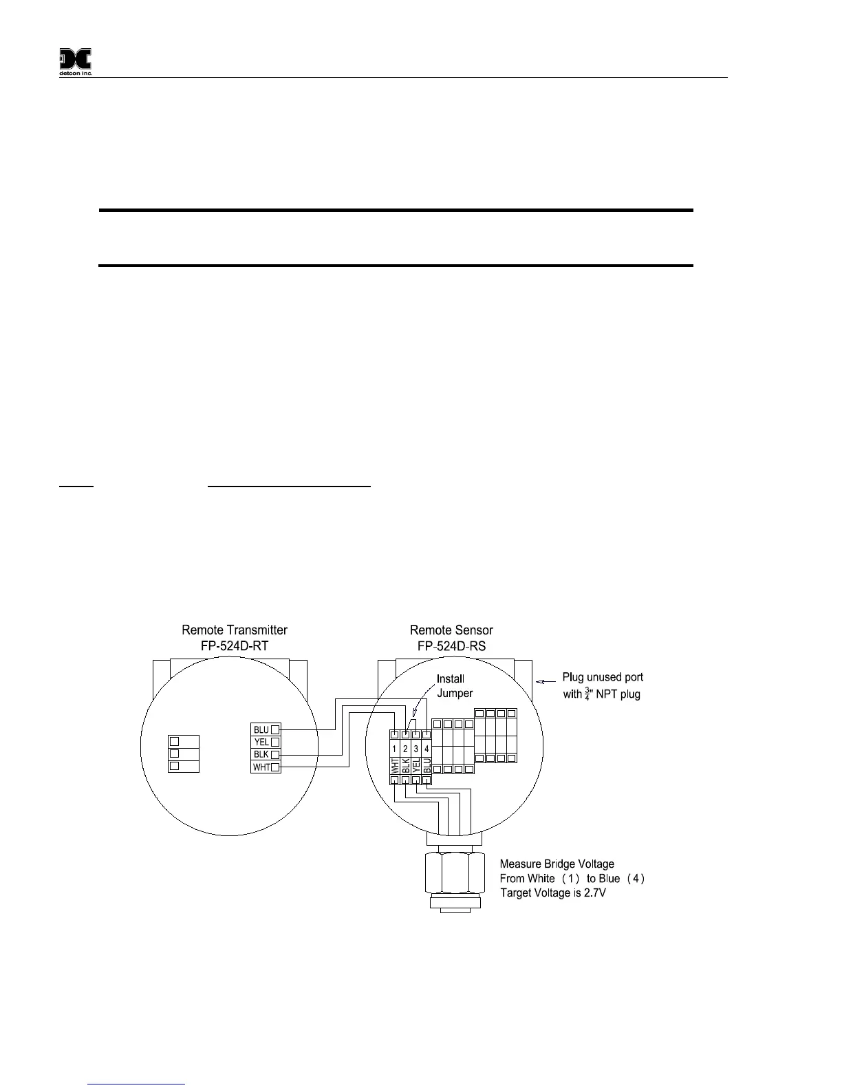
Reference Figure 12 for wiring diagram. Also note the jumper that is required on the remote sensor connector
board. Failure to install this jumper will cause a sensor fault condition.
Figure 12 Remote Sensor Wiring Diagram