© 2007 ITW Finishing Systems and Products 7
E
5. Turn on solvent supply and flush hose and gun by triggering gun or re circulation.
NOTE
: It may be necessary to fit a shut-off valve to the return line on circulating systems and trigger the
gun to clean front portion of the spray head and fluid tip.
Air cap, clean by immersing in solvent, brush or wipe clean. If any holes in the air cap are blocked use a
toothpick or broom straw to remove obstruction. Never use a steel wire or hard implement which will
damage the air cap and result in a distorted pattern.
REPLACEMENT OF PARTS
NOTE: Order numbers shown in parts list for figure 1 with suffix “-K2” etc. at the end of the number
indicates a kit of parts. Example: Ref 5. AGG-88-K2 is a kit of two seals.
TO REMOVE SPRAY HEAD ASSEMBLY See Figure 1.
Disconnect material hose(s). Unscrew the retaining ring and remove the air cap
1. Using a small screwdriver remove the black plastic cover (17) at the top of the spray gun. Check that
the slot in the piston (28) is uppermost so that the fluid needle (16) can be removed. If the slot is not
in the correct position remove knob (36) and use a screwdriver in the center hole of the end cap (35)
to rotate the piston (28) to its correct position.
2. Remove the 4 hexagon socket screws (7) holding the spray head (10) to the body.
3. Pull the spray head (10) forward to disengage the locating pin.
4. Slide the spray head (10) up to disengage fluid needle (16) from piston (28). With spray head
removed all components can easily be removed and replaced.
Material Connectors/Plug (8, 9)
WARNING: To provide protection from the ingress of Halogenated Hydrocarbon materials, the spray
head material passages are sealed. It is essential when fitting connector/plug (8, 9) that sealing
compound is applied and it is tightened to the recommended torque. Do not remove or tighten fluid tip (3)
if connector(s) (8, 9) are not fitted to the spray head, as it may loosen the spray head insert and cause
irreparable damage.
Remove connector(s)/plug with a 6mm hexagon key and clean threads in the spray head. Apply a
medium strength thread locking/sealing compound to the external chamfer and threads of the new
connector. Screw into spray head and tighten. Recommended Torque : 8Nm (70lbf in).
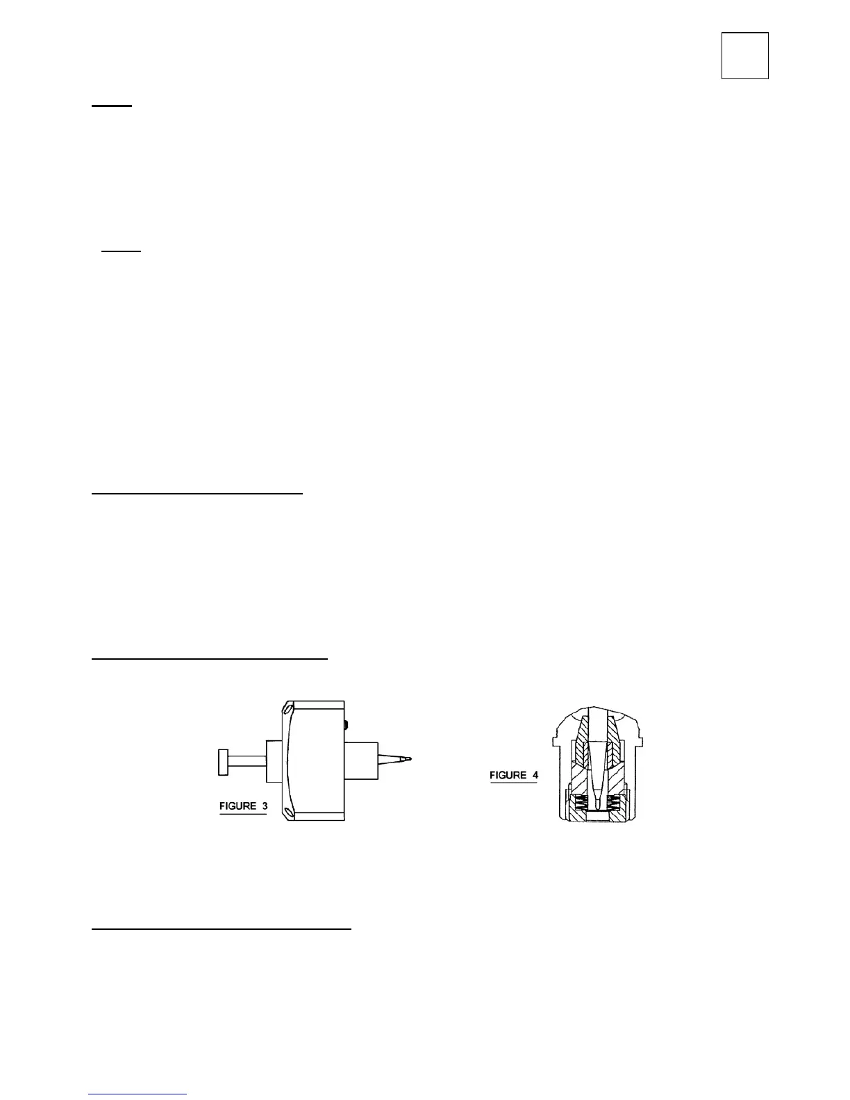
Fluid tip (3) and/or baffle (4 , 5 & 6)
Unscrew the fluid tip (3) remove front and rear baffle (4 & 6) and seals (5, 38), replace if damaged. When
replacing the fluid tip a new seal (5) is required.
Re-assemble ensuring that the fluid tip seats correctly in the spray head. Tighten fluid tip.
Recommended torque 16Nm (140lbf in).
Fluid Needle (16) and Packing Set (12)
To overcome problems experienced with needles jamming, follow this procedure to ensure correct
needle movement and needle packing adjustment. Remove Spray Head Assembly, Fluid Tip (3) and
Baffle (4, 5 and 6) as described.
4.1. Remove needle (16).
4.2. Remove retaining screw (15) using a hexagon key, remove disc springs (14), packing piece (13)
and needle packing set (12) over needle (16). Refer to enlarged view on Figure 1.