SB-2-194-K Page 3
Fluid Tip Size I.D.
Tip No. In. mm
AV-213-10 0.039 1.0
AV-213-12 0.047 1.2
AV-213-13 0.051 1.3
AV-213-14 0.055 1.4
AV-213-16 0.063 1.6
AV-213-18 0.070 1.8
JGA-4035 Packing Replacement Instruc-
tions
1. Remove adjusting knob and needle
spring from gun.
2. Partially withdraw needle from gun
body.
3. Loosen packing nut and remove.
4. Remove old packing.
5. Assemble packing nut to needle
6. Assemble packing in order shown to
needle.
7. Insert needle all the way into gun
body seating in tip.
8. Install needle spring and adjusting
knob.
9. Thread packing nut into gun body.
10. Tighten packing nut in equal
increments - no more than 1/6 turn
at a time.
11. After each adjustment, pull needle
open and observe needle closure.
12. If needle snaps shut, continue
adjusting nut until there is evidence
of needle bind or slow closing.
13. Back off packing nut 1/12 turn to the
point where needle snaps shut.
Packing nut must remain tight
enough to prevent loosening by
hand.
14. Pull needle several times to verify
needle snaps shut and check
packing nut for looseness.
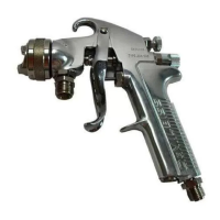
SPRAY GUN LUBRICATION
Daily, apply a drop of SSL-10* spray gun
lube at trigger bearing stud (28) and the
stem of air valve (20) where it enters air valve
assembly. The shank of fluid needle (11)
where it enters packing nut (9) should also
be oiled. Fluid needle packing (8) should be
lubricated periodically. Make sure baffle (6)
and retaining ring (3) threads are clean and
free of foreign matter. Before assembling
retaining ring to baffle, clean the threads
thoroughly, then add two drops of SSL-10
spray gun lube to threads. Fluid needle
spring (14) and air valve spring (19) should
be coated with a very light grease, making
sure that any excess grease will not clog
the air passages. For best results, lubricate
the points indicated, daily.
*Not for air tools or high RPM equipment.
A. Trigger Points
B. Packing
C. Adjusting Knobs
D. Baffle Threads
E. Air Valve Cartridge
PARTS REPLACEMENT
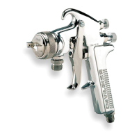
Figure 1 Air Cap
Chart 3
Chart 2
Packing
(3 pieces)
Packing
Nut
Needle
Gun Body
A
B
C
E
D
Air Cap No.
410
DeVilbiss
No. on Air Cap Air Flow (CFM)
Air Cap With Ring @30 @40 @50
Order ➔ (Ref. No. 4) psi psi psi
410 AV-440-410 9.1 11.2 13.2
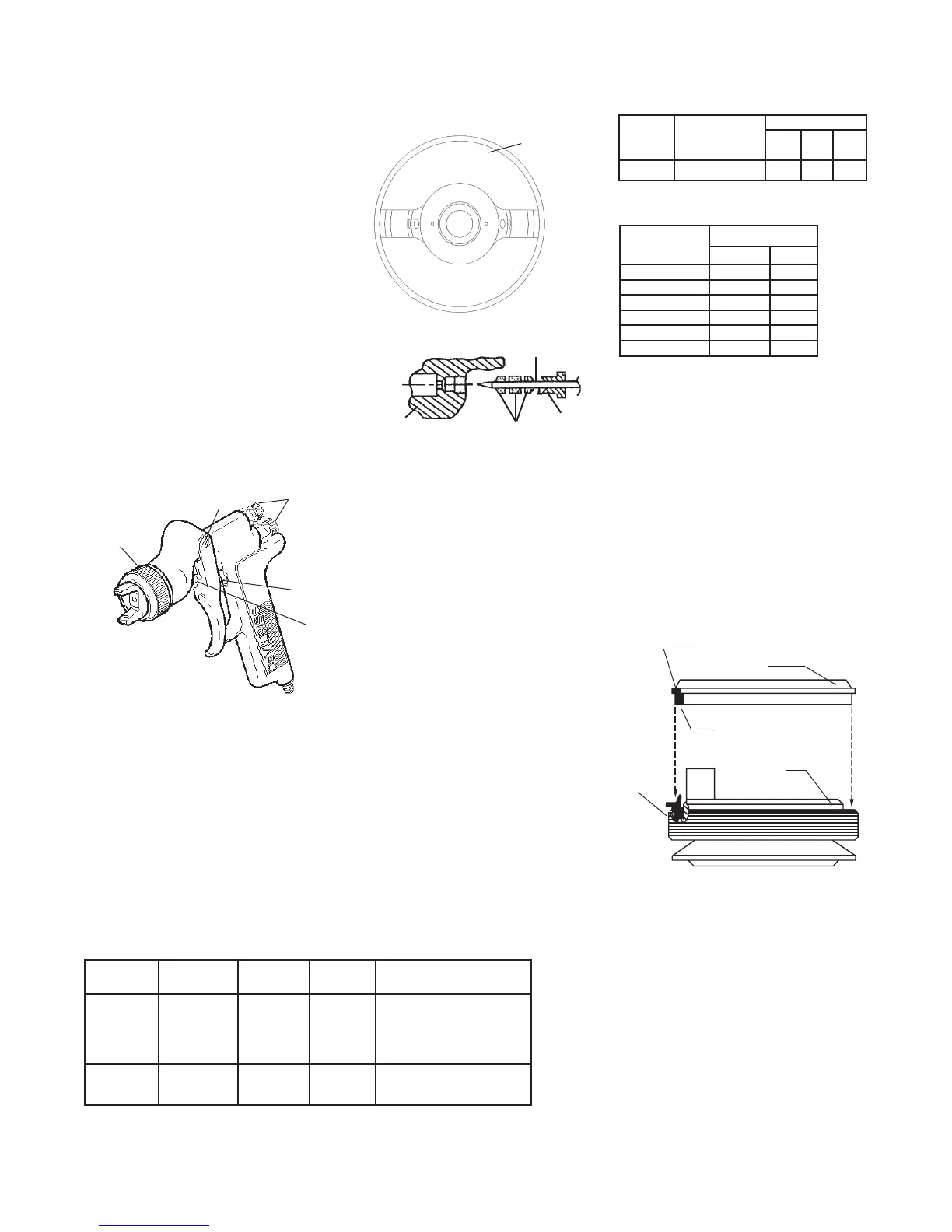
GTI-33 Baffle Seal Replacement
1. Remove Fluid Tip (5).
2. Remove baffle (6).
3. Remove Seal (7) from baffle.
NOTE
The seal is designed to be a tight
fit on the baffle. The seal should
be able to be removed using your
fingers. If you are unable to remove
the seal using your fingers, insert
a small screwdriver between the
outer lip and the back of the baffle
and pry the seal off.
4. Assemble seal to baffle with angled side
up as shown above. NOTE: The seal
should be a tight fit on the baffle. If it is a
loose fit on the baffle, assure that it is
assembled with the angled side up.
5. Install baffle on gun.
6. Install fluid tip (5) and tighten to
15-20 ft-lbs.
ANGLED SIDE
THICK SIDE
SEAL
BAFFLE
Pry here if
necessary
Fluid Tip Inlet Air
Order No. Model No. (mm) Pressure Applications
110264 GFG-670* 1.2 & 1.3 25-35 psi Base coats
30-40 psi High solids clearcoats
30-40 psi Single stages
25-30 psi Waterbornes
1.4 30-40 psi Low solids clear coats
30-40 psi Single stages
*Includes 1.2 mm, 1.3 mm and 1.4 mm fluid tips
Chart 1