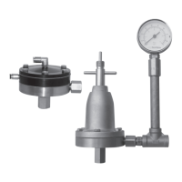
The DeVilbiss HGB-509, HGB-510, and HGB-609 Fluid Regulators are essential components designed to provide consistent material pressure for one or two spray guns. These regulators are particularly well-suited for applications involving low paint viscosity and requiring precise fluid flow regulation, characterized by a low hysteresis level.
Function Description:
These fluid regulators operate by either manual adjustment or remote air pressure control. Their primary function is to maintain a constant fluid pressure, ensuring uniform material delivery to spray guns. This consistency is crucial for achieving high-quality finishes in painting and coating applications. The internal mechanism features a stainless steel ball valve and spring, coupled with a "Perlast" valve seat, which contribute to their durability and precise control.
Important Technical Specifications:
The fluid regulators come in various models, each with specific performance characteristics:
-
HGB-509-5-R38 (Manual Spring):
- Inlet pressure: 2 - 12.5 bar
- Outlet pressure: 5 bar max.
- Fluid flow: 13 L/min max.
- Manometer: No
-
HGB-609-1.2-R38 (Manual Spring):
- Inlet pressure: 1 - 8 bar
- Outlet pressure: 1.2 bar max.
- Fluid flow: 8.3 L/min max.
- Manometer: 0 - 2.5 bar
- Thread: Female 3/8" inlet, Male 3/8" outlet
-
HGB-609-5-R38 (Manual Spring):
- Inlet pressure: 2 - 12.5 bar
- Outlet pressure: 5 bar max.
- Fluid flow: 13 L/min max.
- Manometer: 0 - 6 bar
- Thread: Female 3/8" inlet, Male 3/8" outlet
-
HGB-609-9-R38 (Manual Spring):
- Inlet pressure: 3 - 15 bar
- Outlet pressure: 9 bar max.
- Fluid flow: 13 L/min max.
- Manometer: 0 - 10 bar
- Thread: Female 3/8" inlet, Male 3/8" outlet
-
HGB-510-R1 (Pneumatic Adjustment):
- Inlet pressure: 2 - 15 bar
- Outlet pressure: 15 bar max.
- Fluid flow: 1.6 L/min max. (Tip 1.1mm)
- Manometer: No
- Thread: Female 1/4" inlet, Female 1/4" outlet
-
HGB-510-R2 (Pneumatic Adjustment):
- Inlet pressure: 1 - 15 bar
- Outlet pressure: 7 bar max.
- Fluid flow: 1.3 L/min max. (Tip 1.1mm)
- Manometer: No
- Thread: Female 1/4" inlet, Female 1/4" outlet
-
HGB-510-R4 (Pneumatic Adjustment):
- Inlet pressure: 1 - 15 bar
- Outlet pressure: 4 bar max.
- Fluid flow: 0.8 L/min max. (Tip 1.1mm)
- Manometer: No
- Thread: Female 1/4" inlet, Female 1/4" outlet
-
HGB-510-R1-CO (Pneumatic Adjustment):
- Inlet pressure: 2 - 15 bar
- Outlet pressure: 15 bar max.
- Fluid flow: 1.6 L/min max. (Tip 1.1mm)
- Manometer: No
- Thread: Male 3/8" inlet, Female 3/8" outlet
-
HGB-510-R2-CO (Pneumatic Adjustment):
- Inlet pressure: 1 - 15 bar
- Outlet pressure: 7 bar max.
- Fluid flow: 1.3 L/min max. (Tip 1.1mm)
- Manometer: No
- Thread: Male 3/8" inlet, Female 3/8" outlet
-
HGB-510-R4-CO (Pneumatic Adjustment):
- Inlet pressure: 1 - 15 bar
- Outlet pressure: 4 bar max.
- Fluid flow: 0.8 L/min max. (Tip 1.1mm)
- Manometer: No
- Thread: Male 3/8" inlet, Female 3/8" outlet
All fluid passages are constructed from stainless steel (303), with a PTFE membrane and an aluminum nickel-treated cover for manual models, or an anodized cover for remote air control. The HGB-609 regulators include a stainless steel tee and riser tube for a manometer.
Usage Features:
- Installation: Regulators should be fitted horizontally to prevent heavy fluid particle deposits. The manometer's riser tube must be vertical to protect the manometer from air. Proper sealing of connectors is essential to prevent air leakage.
- Fluid Line Connection: Connect the fluid supply line (from pump or pressure feed tank) to the regulator's inlet (1/4" BSP or 3/8" NPS/BSP universal, depending on the version). The regulated fluid line, supplying one or two spray guns, connects to the side port of the regulator. "CO" versions use a swivel connector female for remote control.
- Earthing: The regulator must be earthed to dissipate electrostatic charges generated by fluid or air flows, typically via screw ref 3A or 3B. An ohmmeter check should confirm resistance below 10^6 Ohms.
- Initial Fill: During installation, ensure the regulator's cavity under the diaphragm is completely filled to achieve accurate regulation, especially at lower fluid flow deliveries.
- Inline Filter: It is recommended to use an inline filter during initial installation to prevent pipe compound chips, scale, or other debris from lodging on the valve seat.
- Manual Regulator Operation: Fluid pressure is adjusted using a specific manual key. Insert the square side of the key into the central top hole of the regulator. Screw in to increase pressure, unscrew to decrease.
- Flushing (Manual Regulator): For cleaning, introduce the cylindrical side of the key into the regulator and screw it to maximum to push the pin on the membrane support, opening the regulator for optimum flushing fluid flow.
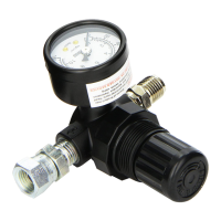
- Pneumatic Adjustment Regulator Operation (HGB-510): Fluid pressure is adjusted via a remote air pressure regulator connected to the top connector on the cover. To flush the regulator, connect an air tube to the side connector (R1/R2/R4) and set air pressure to fully open the valve. For accurate regulation at low fluid flow, it's beneficial to fit the air regulator close to the fluid regulator. A small air leakage can be created by piercing the Rilsan tube with a sewing needle near the connector.
- Flushing (Pneumatic Regulator): Connect the flushing air command to the right connector on the side of the regulator. CAUTION: Do not exceed the flushing air command by more than 1 bar over the solvent pressure.
- Air Purging: After cleaning, purge the air line to remove air pressure from the intermediary chamber. This chamber can act as a safe area if the membrane breaks and fluid leakage occurs through the air line.
- Model Identification: An arrow on the cover indicates the regulator model, either pointing towards the flushing air inlet connector for R1 models or towards the 1/4 or 1/2 markings on the intermediary plate. Ensure correct cover placement during reassembly.
Maintenance Features:
- Preventive Maintenance: Regular cleaning with a compatible solvent is recommended.
- Relieve supply line pressure.
- Put the regulator in flushing position (valve off its seat).
- Blow material back through the regulated line by introducing air pressure downstream from the regulator (e.g., by loosening the air cap ring on a spray gun, holding a rag over the air cap, and pulling the trigger). This forces air in reverse through the spray gun and material back through the regulated line.
- Unscrew the fluid inlet connector, remove the spring and ball valve. Clean all parts and the gasket. Replace damaged gaskets. If the gasket is in good condition, apply thread locking compound (Loctite 222) to the connector thread and tighten to a maximum torque of 6.4Nm.
- Periodically clean the exterior of the regulator with a solvent-soaked rag.
- Replacing Diaphragm:
- Relieve line pressure (pneumatic models) or spring forces by unscrewing the adjusting screw (manual models).
- Remove the 6 hex head cap screws.
- The diaphragm is sold as a complete unit with its washer and fluid flow plastic deflector. Replace the entire unit if damaged.
- Install the new diaphragm kit into the regulator body.
- Place the cover on the regulator and screw the 6 screws at 7.5 to 8 mN.
- For pneumatic HGB510 models, reassemble all parts in the correct order and position. It's recommended to cycle the two diaphragms about 10 times by using connector Rep 8 and pressurizing the flushing cavity at 4 bar to ensure full conditioning.
- Servicing Valve Assembly ("Perlast D shape" seat and Ball valve):
- Unscrew the fluid inlet valve and connector Rep 16 from the regulator body.
- Clean and check the valve. Replace parts using the valve kit if damaged.
- Fit the washer in the correct position (small dimension in front of the "D" gasket). Screw the valve body onto the regulator body with Loctite 270 on the third thread and tighten to a maximum torque of 12Nm. Do not overtighten to avoid damage.
- Wait a few minutes for the Loctite to dry, then fit the ball valve and spring.
- Clean the thread on the fluid inlet connector, use Loctite 222, and apply a maximum torque of 6.4Nm.
Safety Warnings:
Users must adhere to all local and national safety codes, including those for ventilation, fire precautions, operation, maintenance, and housekeeping.
- Fire and Explosion: Solvents and coating materials are flammable. Ensure adequate ventilation, avoid smoking/naked flames, and have fire extinguishing equipment.
- Halogenated Hydrocarbon Solvents: These can react with aluminum and galvanized/zinc-coated parts, causing explosions. Only use equipment specifically designed for such solvents.
- Static Electricity: Fluid movement generates static electricity. Ensure earth continuity for all equipment (resistance below 10^6 ohm).
- Personal Protective Equipment: Wear eye protection and gloves when spraying or cleaning. Use appropriate respiratory protective equipment.
- Training: Personnel must be adequately trained in the safe use and maintenance of this equipment.
- Misuse: Never exceed recommended safe working pressures. Do not use non-recommended or non-original accessories. Always isolate and release all pressures (air and material) before dismantling for cleaning or maintenance.
- Disposal: Dispose of non-metallic materials, waste solvents, and coating materials through authorized services.
- Solvent Compatibility: The fluid section materials are solvent-resistant. However, do not immerse the regulator or manometer in gun washing machines, as this can damage gaskets or membranes. Regularly check solvents in gun washing machines for contamination.
These regulators are classed as components by the ATEX directive 94/9/EC, with protection level II 2 G, and conform to EN 292-1 PARTS 1 & 2: 1991, EN 1953: 1999, and Council Directive 98/37/EC.