ENGLISH
6
FIG. D
8
Cooling System
This compressor contains an advanced design cooling
system. At the heart of this cooling system is an engineered
fan. It is perfectly normal for this fan to blow air through
the vent holes in large amounts. You know that the cooling
system is working when air is being expelled.
Air Compressor Pump
The pump compresses air into the air tank. Working air is
not available until the compressor has raised the air tank
pressure above that required at the air outlet.
Motor Overload Protector
The motor has a thermal overload protector. If the motor
overheats for any reason, the overload protector will shut off
the motor. The motor must be allowed to cool down before
restarting. To restart:
1. Set the On/Off switch
1
to OFF and unplug unit.
2. Allow the motor to cool.
3. Plug the power cord into the correct branch circuit
receptacle.
4. Set the On/Off switch to ON position.
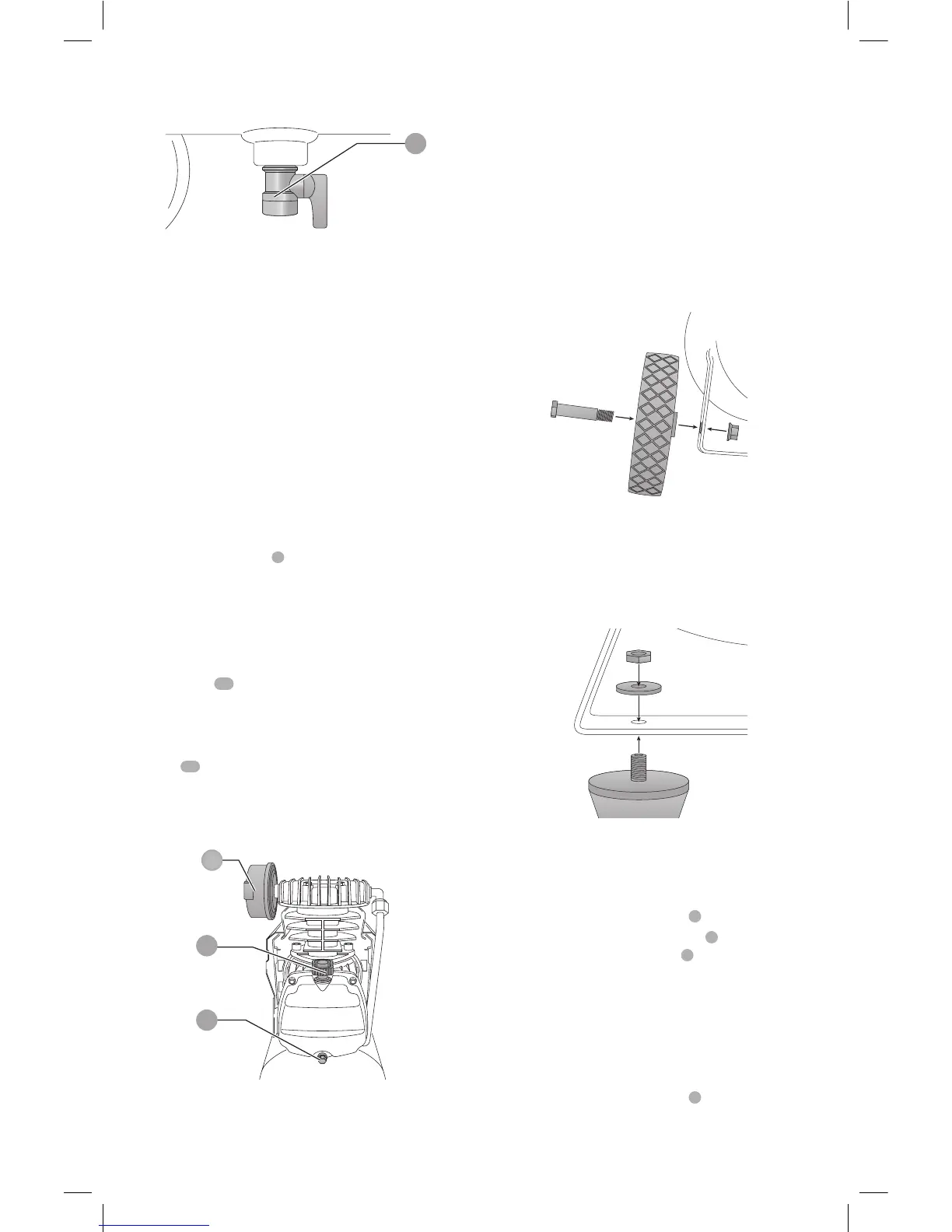
Oil Dipstick
The oil dipstick
10
indicates the amount of oil in the pump.
Check pump oil daily, see Compressor Pump Oil under
Maintenance.
Air Intake Filter
The filter
12
is designed to clean air entering the pump.
To ensure the pump continually receives a clean, cool, and
dry air supply the filter must always be clean and the filter
intake must be free from obstructions.
10
12
11
FIG. E
ASSEMBLY
You must assemble the compressor before using it for the
first time.
Fitting the Wheels and Bumpers
(Fig. F, G)
Fit the supplied wheels:
1. Insert the bolt through the wheel and bracket as shown
in Fig. F.
2. Holding the locking nut in place with a wrench, tighten
the wheel bolt securely.
3. Repeat these steps for the opposite wheel.
FIG. F
Attach the bumpers:
1. Align the bumper threads with washer and nut as
shown in Fig. G.
2. Insert threaded shaft through the bracket hole tighten
bolt securely.
3. Repeat these steps for the opposite bumper.
FIG. G
Installing Hoses (Fig. C)
WARNING: Risk of unsafe operation. Firmly grasp
hose in hand when installing or disconnecting to
prevent hose whip.
1. Ensure Regulated Pressure Gauge
3
reads 0 psi.
2. Grasp the hose at the Quick Connect
5
plug and push
the plug into the Quick Connect
5
body. Coupler will
snap into place.
3. Grasp the hose and pull to ensure coupler is seated.
Disconnecting Hoses (Fig. C)
WARNING: Risk of unsafe operation. Firmly grasp
hose in hand when installing or disconnecting to
prevent hose whip.
1. Ensure Regulated Pressure Gauge
3
reads 0 psi.