• Do not incinerate the battery pack even if it
is
severely damaged or is completely worn
out.
The battery pack can explode in a fire.
• A small leakage of liquid from the battery
pack
cells may occur under extreme usage
or
temperature conditions . This does not
indicate
a failure.
However, if the outer seal is broken:
a.
and the battery liquid gets on your skin,
immediately
wash with soap and water for
several
minutes.
b. and the battery liquid gets into your eyes,
flush
them with clean water for a minimum
of
10 minutes and seek immediate medical
attention.
(Medical note: The liquid is
25-35%
solution of potassium hydroxide.)
Battery Cap (fi g. 3)
A protective battery cap is supplied to cover the
contacts
of a detached battery pack. Without the
protective cap in place, loose metal objects could
short
circuit the contacts, causing a fire hazard and
damaging
the battery pack.
1. Take off the protective battery cap before
placing
the battery pack in the charger
or
tool (Fig. 3A).
2. Place the protective cap over the contacts
immediately
after removing the battery pack
from the charger or tool (Fig. 3B).
WARNING: Make sure the protective
batte
ry cap is in place before storing or
car
rying a detached battery pack.
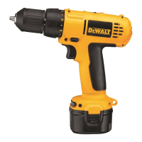
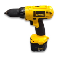
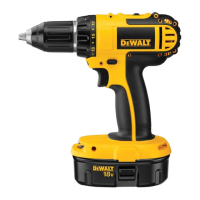
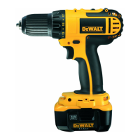
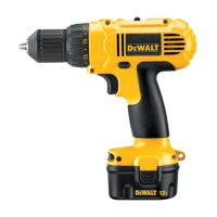
Battery pack (fi g. 1)
BATTERY TYPE
Each tool described in this manual uses different battery
platforms within the DEWALT battery system.
Users of existing 12V, 14.4V & 18V batteries can use their
packs on the relevant tools in this manual.
Performance & run time may vary slightly on pack used.
Labels on charger and battery pack
Battery charging.
Battery charged.
Battery defective.
Hot/cold pack delay.
Do not probe with conductive objects.
Do not charge damaged battery packs.
Use only with D EWALT battery packs,
others
may burst, causing personal injury
and
damage.
Do not expose to water.
Have defective cords replaced
immediatel
y.
Charge only between 4 °C and 40 °C.
Discard the battery pack with due care for
the
environment.
Do not incinerate the battery pack
NiMH,
NiCd+ and Li-Ion.
Charges NiMH and NiCd
battery
packs.
MAINTENANCE
Separate collection. This product must
not be disposed of with normal
household
waste.
CHARGER
CLEANING INSTRUCTIONS
WARNING: Shock hazard. Disconnect
the
charger from the AC outlet before
cleaning. Dirt and grease may be
removed
from the exterior of the charger
using
a cloth or soft non-metallic brush.
Do not use water or any cleaning
solutions
.
Rechargeable Battery Pack
This long life battery pack must be recharged when
it
fails to produce sufficient power on jobs which
we
re easily done before. At the end of its technical
life,
discard it with due care for our environment:
Package contents
The package contains:
1 Drill/Hammerdrill
2 Battery packs
1 Charger
1 Kitbox (K version only)
1 Instruction manual
1 Exploded drawing
NOT
E : Battery packs and chargers are not included
with
N-models.
• Check for damage to the tool, parts or
accessories
which may have occurred during
transport
.
• Take the time to thoroughly read and
understand
this manual prior to operation.
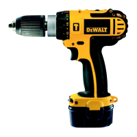
Description (fi g. 1)
INTENDED USE
These
drills/drivers/hammerdrills are designed for
professional drilling and screwdriving applications.
a. Trigger switch
b. Forward/reverse button
c. Torque adjustment collar
d. Gear selector
e. Worklight
f. Keyless chuck
g. Battery pack
h. Battery release buttons
Inserting and removing the
batte
ry pack from the tool (fi g. 2)
WARNING: To reduce the risk of
serious
personal injury, turn tool off
and
disconnect battery pack before
making
any adjustments or removing/
installing
attachments or accessories.
An
accidental start-up can cause injury.
TO
INSTALL BATTERY PACK INTO THE TOOL HANDLE
1. Align the base of the tool with the notch inside
the
tool’s handle (fig. 2).
2. Slide the battery pack firmly into the handle until
you
hear the lock snap into place.
TO
REMOVE BATTERY PACK FROM THE TOOL
1. Press the battery release buttons (h) and firmly
pull
the battery pack out of the tool handle.
2. Insert battery pack into the charger as
described
in the charger section of this manual.
Variable Speed Switch (fi g. 1)
To turn the tool on, squeeze the trigger switch (a).
To turn the tool off , release the trigger switch. Your
tool
is equipped with a brake. The chuck will stop as
soon
as the trigger switch is fully released.
NOTE:
Continuous use in variable speed range is
not
recommended. It may damage the switch and
should
be avoided.
Forward/Reverse Control Button
(fi
g. 1)
A forward/reverse control button (b) determines the
di
rection of the tool and also serves as a lock off
button.
To select forward rotation, release the trigger
switch
and depress the forward/reverse control
button
on the right side of the tool.
To select reverse, depress the forward/reverse
cont
rol button on the left side of the tool.
NOTE
: The first time the tool is run after changing
the
direction of rotation, you may hear a click on
start
up. This is normal and does not indicate a
problem.
Torque Adjustment Collar (fi g. 1)
Your tool has an adjustable torque screwdriver
mechanism
for driving and removing a wide array of
fastener
shapes and sizes and in some models, a
hammer
mechanism for drilling into masonry. Circling
the collar (c) are numbers, a drill bit symbol, and in
some
models, a hammer symbol. These numbers
are used to set the clutch to deliver a torque range.
The
higher the number on the collar, the higher the
to
rque and the larger the fastener which can be
driven.
To select any of the numbers, rotate until the
desi
red number aligns with the arrow.
Dual Range Gearing (fi g. 1)
To select the low speed, high torque setting, turn
the
tool off and permit to stop. Slide the gear
selector
(d) forward (towards the chuck) as shown
in
Figure 1.
To select the high speed, low torque setting, turn the
tool
off and permit to stop. Slide the gear selector
back
(away from chuck).
Worklight (fi g. 1)
There is a worklight (e) located just above the trigger
switch
(a). The worklight will be activated when the
trigger
switch is squeezed.
Keyless Single Sleeve Chuck (fi g. 1)
1. Lock the trigger in the OFF position as
previously described.
2. Grasp the black sleeve of the chuck with one
hand
and use the other hand to secure the tool.
Rotate
the sleeve counterclockwise far enough
to
accept the desired accessory.
3. Insert the accessory about 19 mm into the
chuck
and tighten securely by rotating the
chuck
sleeve clockwise with one hand while
holding
the tool with the other. Your tool is
equipped
with an automatic spindle lock
mechanism.
This allows you to open and close
the
chuck with one hand.
To release the accessory, repeat step 2 above.
Hammerdrill Operation (fi g. 5)
1. Turn the collar (c) to the hammerdrill symbol.
2. Select the high speed setting by sliding the
selector
back (away from the chuck).
IMPORTANT: Use carbide-tipped or masonry
bits
only.
Screwdriver Operation (fi g. 6)
1. Select the desired speed/torque range using the
dual
range gear selector to match the speed
and
torque of the planned operation.
2. Turn the torque adjustment collar to the desired
position.
Lower numbers indicate lower torque
settings;
higher numbers indicate higher torque
settings
.
 Loading...