11
ENGLISH
LED Worklight (Fig.E)
The LED worklight
9
and its worklight switch
10
are located on
the foot of the tool. The worklight is activated when the trigger
switch is depressed. The low, medium, and spotlight modes can
be changed by moving the switch on the foot of the tool. If the
trigger switch remains depressed, the worklight will remain on
in allmodes.
When on low and medium settings, the beam will automatically
turn off 20 seconds after the trigger switch isreleased.
Three-Speed Gearing (Fig.A)
The three-speed feature of your tool allows you to shift gears
for greater versatility. To select speed 1 (highest torque setting),
turn the tool off and permit it to stop. Slide the gear shifter
8
all the way forward. Speed 2 (middle torque and speed setting)
is in the middle position. Speed 3 (highest speed setting) is to
therear.
NOTE: Do not change gears when the tool is running. Always
allow the drill to come to a complete stop before changing
gears. If you have trouble changing gears, make sure that the
gear shifter is engaged in one of the three speedsettings.
If the speed shifter becomes stuck or is difficult to select the
desired gear, pull the variable speed trigger switch
3
to rotate
the motor, then select thegear.
Torque Adjustment Collar/Electronic Clutch
(Fig.A)
Your tool has an electronic adjustable torque screwdriver
mechanism for driving and removing a wide array of fasteners.
Circling the torque adjustment collar
5
are numbers. These
numbers are used to set the clutch to deliver a torque range.
The higher the number on the collar, the higher the torque and
the larger the fastener which can be driven. To select any of the
numbers, rotate until the desired number aligns with thearrow.
WARNING: When the torque adjustment collar is in the
drill or hammerdrill positions, the drill will not clutch. The
drill may stall if overloaded, causing a suddentwist.
Forward/Reverse Control Button (Fig.A)
A forward/reverse control button
4
determines the direction of
the tool and also serves as a lock-offbutton.
To select forward rotation, release the trigger switch and
depress the for ward/re verse control button on the right side of
thetool.
To select reverse, release the trigger switch and depress the
forward/reverse control button on the left side of thetool.
The centre position of the control button locks the tool in the off
position. When changing the position of the control button, be
sure the trigger isreleased.
NOTE: The first time the tool is run after changing the direction
of rotation, you may hear a click on start up. This is normal and
does not indicate aproblem.
If model is not equipped with side handle, grip drill with one
hand on the handle and one hand on the batterypack.
NOTE: Side handle comes equipped on allmodels.
Variable Speed Trigger Switch (Fig.A)
To turn the tool on, squeeze the variable speed
triggerswitch
3
. To turn the tool off, release the trigger switch.
Your tool is equipped with a brake. The chuck will stop as soon
as the trigger switch is fullyreleased.
NOTE: Continuous use in variable speed range is not
recommended. It may damage the switch and should
beavoided.
Belt Hook and Magnetic Bit Holder (Fig.A)
Optional Accessories
WARNING: To reduce the risk of serious personal
injury, ONLY use the tool's belt hook to hang the
tool from a work belt. DO NOT use the belt hook for
tethering or securing the tool to a person or object during
use. DO NOT suspend tool overhead or suspend objects
from the belthook.
WARNING: To reduce the risk of serious personal
injury, ensure the screw holding the belt hook issecure.
CAUTION: To reduce the risk of personal injury or
damage, DO NOT use the belt hook to hang the drill
while using as aspotlight.
IMPORTANT: When attaching or replacing the belt hook
11
or
magnetic bit holder
13
, use only the mounting screw
12
that
is provided. Be sure to securely tighten thescrew.
The belt hook and magnetic bit holder can be be attached
to either side of the tool using only the screw provided, to
accommodate left- or right- handed users. If the hook or
magnetic bit holder is not desired at all, it can be removed from
thetool.
To move belt hook or bit clip, remove the screw that holds it in
place then reassemble on the opposite side. Be sure to securely
tighten thescrew.
To actuate the fuel gauge, press and hold the fuel gauge
button
17
. A combination of the three green LED lights will
illuminate designating the level of charge left. When the level
of charge in the battery is below the usable limit, the fuel gauge
will not illuminate and the battery will need to berecharged.
NOTE: The fuel gauge is only an indication of the charge left on
the battery pack. It does not indicate tool functionality and is
subject to variation based on product components, temperature
and end-userapplication.
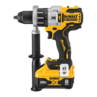
Side Handle (Fig.A, D)
WARNING: To reduce the risk of personal injury, ALWAYS
operate the tool with the side handle properly installed.
Failure to do so may result in the side handle slipping
during tool operation and subsequent loss of control. Hold
tool with both hands to maximizecontrol.
The side handle
14
clamps to the front of the gear case and
may be rotated 360˚ to permit right- or left-hand use. Side
handle must be tightened sufficiently to resist the twisting
action of the tool if the accessory binds or stalls. Be sure to grip
the side handle at the far end to control the tool during astall.
 Loading...