ENGLISH
8
COMPONENTS (FIG. A)
WARNING: Never modify the power tool or any part
of it. Damage or personal injury couldresult.
Refer to Figure A at the beginning of this manual for a
complete list ofcomponents.
Intended Use
This cordless pencil vibrator is designed for professional
vibrationapplications.
DO NOT use under wet conditions or in the presence of
flammable liquids, gases, ordusts.
This cordless pencil vibrator is a professional power tool.
DO NOT let children come into contact with the tool.
Supervision is required when inexperienced operators use
thistool.
ASSEMBLY AND ADJUSTMENTS
WARNING: To reduce the risk of serious personal
injury, turn unit off and remove the battery pack
before making any adjustments or removing/
installing attachments or accessories. An
accidental start-up can causeinjury.
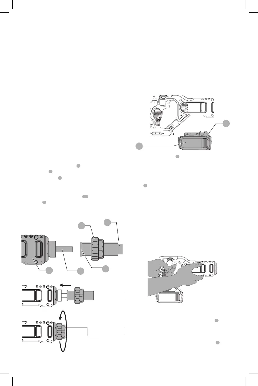
Attaching the Shaft (D, E)
1. Ensure that the plastic collar
7
is inserted over the flex
shaft casing
6
as shown in FigureD.
2. Insert the spindle
9
into the flex shaftopening.
3. Manuevre the flex shaft back and forth until the parts
slide together (Fig.E).
4. Ensure that the flex shaft flange
10
is snug against
housing
3
.
5. Firmly tighten the collar by hand (Fig.E). Do not use a
wrench totighten.
3
9
10
6
7
Fig. D
Fig. E
OPERATION
WARNING: To reduce the risk of serious personal
injury, turn unit off and remove the battery pack
before making any adjustments or removing/
installing attachments or accessories. An
accidental start-up can causeinjury.
Installing and Removing the Battery Pack
(Fig. F)
NOTE: For best results, make sure your battery pack is
fullycharged.
Fig. F
8
9
To install the battery pack
8
into the tool handle, align the
battery pack with the rails inside the tool’s handle and slide
it into the handle until the battery pack is firmly seated in
the tool and ensure that it does notdisengage.
To remove the battery pack from the tool, press the release
button
9
and firmly pull the battery pack out of the tool
handle. Insert it into the charger as described in the charger
section of thismanual.
Proper Hand Position (Fig. G)
WARNING: To reduce the risk of serious personal injury,
ALWAYS use proper hand position as shown.
WARNING: To reduce the risk of serious personal
injury, ALWAYS hold securely in anticipation of a
suddenreaction.
Proper hand position requires one hand on the main handle
and one hand on the main housing for stability.
Fig. G
Trigger Switch (Fig. A)
To turn the tool “ON”, squeeze the trigger switch
1
. To turn
the tool “OFF” release the triggerswitch.
Lock-Off Button (Fig. H)
To select Locked/Off, depress the lock-off button
2
on the
left side of the tool. When changing the position of the lock-
off button, be sure the trigger isreleased.