35
ENGLISH
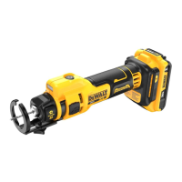
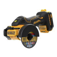
On/off Button (Fig. A)
• To start the motor, press the on/off button
1
.
• To stop the motor, press the on/off button
1
again.
Attaching the Dust Shroud (Fig. A, F)
The DCE555DC dust shroud is also available for use with this
tool. This accessory connects to the tools cutting depth guide to
function as both a cutting depth guide and a dust shroud. It is
compatible with the DWH161 DeWALT Universal Dust Extractor
(soldseparately).
To attach the dust shroud, FIRST turn off the tool and disconnect
the battery from thetool.
1. Remove the cutting depthguide
2
.
2. Fully unscrew the knob and separate the knob
16
and the
washer
17
from the cutting depth guide
2
.
Proper Hand Position (Fig. D)
WARNING: To reduce the risk of serious personal injury,
ALWAYS use proper hand position as shown.
WARNING: To reduce the risk of serious personal injury,
ALWAYS hold securely in anticipation of a suddenreaction.
WARNING: Tool may stall (if overloaded or improperly
used) causing a twist. Always expect the stall. Grip the tool
firmly with both hands to control the twisting action and
prevent loss of control which could cause personalinjury.
Proper hand position requires one hand on the handle
15
and
the other bracing the battery to control the twisting action of
thetool.
OPERATION
Instructions for Use
WARNING: Always observe the safety instructions and
applicableregulations.
WARNING: To reduce the risk of serious personal
injury, turn tool off and disconnect battery pack
before making any adjustments or removing/
installing attachments or accessories. An accidental
start-up can causeinjury.
Belt Clip (Fig. C)
WARNING: To reduce the risk of serious personal injury,
ensure the screw holding the belt clip issecure.
IMPORTANT: When attaching or replacing the belt clip
11
,
use only the screw
12
that is provided. Be sure to securely
tightenscrew.
If the belt clip is not desired at all, it can be removed from
thetool.
To remove the belt clip, remove the screw
12
that holds the belt
clip inplace.
3. Replace the front portion of the cutting depth guide with
the dust shroud
14
.
4. Rethread the washer and the knob and tighten into the base
of the cutting depthguide.
5. Snap dust shroud/cutting depth guide onto thetool.
Attaching a Dust Extractor to the Dust Shroud
(Fig.G)
The DCE555DC dust shroud is compatible with the DWH161
DEWALT Universal Dust Extractor (soldseparately).
• Friction‑fit the the dust shroud
14
port to the hose
18
of
the DWH161 Universal DustExtractor.
Depth Guide (Fig. A)
Cutting depth guide
2
snaps onto locators as shown. Keep
depth guide in place at all times during operation of the tool.
For best results, adjust the cutting depth guide using the knob
to allow the bit to protrude about 6.35mm past the thickness of
material to be cut. Ensure that when cutting, the entire material
thickness will engage with the bit'sflutes.
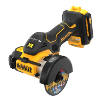
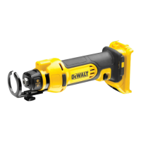
Installing and Removing the Bit (Fig. A)
This tool is designed for spiral cutting bits with either a 3mm
(1/8"), 4mm (5/32") (4mm collet sold separately), or 6mm
(1/4") shank and has a tool‑free bit change system. To change
bits, FIRST turn off the tool and disconnect the battery from the
tool. Remove the cutting depth guide
2
.
1. To replace bit, depress both spindle lock button
7
and
collet lock
5
and turn collet grip
6
counterclockwise.
2. Insert or removebit.
WARNING: The bits are sharp and should be handled
with greatcare.
CAUTION: When replacing bits, do not insert cutting
flutes into the collet. This may result in brokenbits.
3. While depressing both spindle and collet locks, turn the
collet grip clockwise to firmly tighten the collet. For some
heavy duty applications, it may be necessary to use a
wrench to further tighten the collet nut
4
while depressing
the spindle lock button
7
.
4. Reattach the cutting depthguide.
CAUTION: Never tighten the collet without a bitinstalled.
This tool comes with both 3mm (1/8") and 6mm (1/4")
collets. To change collets, remove the collet nut and insert the
desiredcollet. Always use a collet with a matching diameter to
that of the bit beinginstalled.
To actuate the fuel gauge, press and hold the fuel gauge
button
21
. A combination of the three green LED lights will
illuminate designating the level of charge left. When the level
of charge in the battery is below the usable limit, the fuel gauge
will not illuminate and the battery will need to berecharged.
NOTE: The fuel gauge is only an indication of the charge left on
the battery pack. It does not indicate tool functionality and is
subject to variation based on product components, temperature
and end‑userapplication.