10
ENGLISH
ASSEMBLY AND ADJUSTMENTS
WARNING: To reduce the risk of serious personal
injury, turn tool off and disconnect battery pack
before making any adjustments or removing/
installing attachments or accessories. An accidental
start-up can causeinjury.
WARNING: Use only DEWALT battery packs andchargers.
Inserting and Removing the Battery Pack
from the Tool (Fig. B)
NOTE: Make sure your battery pack
14
is fullycharged.
To Install the Battery Pack into the Tool Handle
1. Align the battery pack
14
with the rails inside the tool’s
handle (Fig. B).
2. Slide it into the handle until the battery pack is firmly seated
in the tool and ensure that you hear the lock snap intoplace.
To Remove the Battery Pack from the Tool
1. Press the release button
15
and firmly pull the battery pack
out of the toolhandle.
2. Insert battery pack into the charger as described in the
charger section of thismanual.
Fuel Gauge Battery Packs (Fig. B)
Some DEWALT battery packs include a fuel gauge which
consists of three green LED lights that indicate the level of
charge remaining in the batterypack.
To actuate the fuel gauge, press and hold the fuel gauge
button
16
. A combination of the three green LED lights will
illuminate designating the level of charge left. When the level
of charge in the battery is below the usable limit, the fuel gauge
will not illuminate and the battery will need to berecharged.
NOTE: The fuel gauge is only an indication of the charge left on
the battery pack. It does not indicate tool functionality and is
subject to variation based on product components, temperature
and end-userapplication.
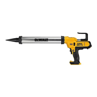
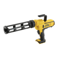
The DCE560, DCE571, DCE580 and DCE581 cordless material
dispensers come fullyassembled.
• The DCE560 accepts 300-310 ml. cartridges.
• The DCE571 accepts 300-310ml cartridges or 400ml
sausagepacks.
• The DCE580 accepts 300-310ml cartridges, 400ml or 600ml
sausagepacks.
• The DCE581 accepts 300-310ml cartridges, 400ml or 600ml
sausagepacks.
To Change Material Holders (Fig. C)
An alternate material holder is available at extra cost from your
local dealer or authorized service centre. Refer to Accessories for
contactinformation.
1. Using a screwdriver, remove the screw
17
and separate the
plunger
7
from the plunger rod
5
.
2. Loosen the material holder from the mounting collar and
remove the material holder.
3. Depress and hold the plunger rod release trigger
6
and pull
the plunger rod completely out from the unit.
4. With plunger rod release trigger depressed, insert new
plunging rod into theunit.
5. Screw the new material holder into the mountingcollar.
6. Install screw through the plunger onto the end of the
plungingrod.
OPERATION
Instructions for Use
WARNING: Always observe the safety instructions and
applicableregulations.
WARNING: To reduce the risk of serious personal
injury, turn tool off and disconnect battery pack
before making any adjustments or removing/
installing attachments or accessories. An accidental
start-up can causeinjury.
Proper Hand Position (Fig. D)
WARNING: To reduce the risk of serious personal injury,
ALWAYS use proper hand position asshown.
WARNING: To reduce the risk of serious personal
injury, ALWAYS hold securely in anticipation of a
suddenreaction.
Proper hand position requires one hand on the main handle
Refer to Fig D.
Variable Speed Dial (Fig. E)
The material's rate of flow is controlled by the variable speed
dial
3
to accomodate variousapplications.
• Pick a speed by turning the dial to the desired setting.
NOTE: '1' is the lowest (slowest) setting and '6' is the
highest (fastest)setting.
Variable Speed Trigger (Fig. F)
In addition to the variable speed dial, the material's rate of flow
is also controlled with a variable speed trigger.
1. Squeeze the trigger switch
1
to turn the toolon.
NOTE: The further the trigger is depressed the faster the
rate offlow.
2. Release the trigger switch to turn the tool off.
Trigger Switch Lock-off (Fig. F)
Your tool is equipped with a trigger switch lock-off
2
to
safeguard against inadvertent release ofmaterial.
1. To lock the trigger switch, push trigger switch lock-off
2
up. The tool will not operate with the switch in the
lockedposition.
2. To unlock the trigger switch, push the trigger switch lock-
offdown.
Rotating Cartridge Holder (Fig. G)
The cartridge holder
8
rotates 360˚ to apply material at
anyangle.
 Loading...