11
ENGLISH
Vacuum indicators
18
display red (Fig. F–I)
When the vacuum button
8
is deactivated, the vacuum
indicators
18
will illuminate red and blink.
1. To release the load, deactivate vacuum pump by pressing
the vacuum button
8
. The vacuum indicators
18
will
illuminate red and blink rapidly.
2. Slide trigger lock button
10
forward and press and hold
the release button
9
to vent the vacuum pressure and
release the load.
3. The four vacuum indicators
18
will stop illuminating in
sequence as the pressure drops.
LED screen flashing and low battery chime (Fig. I)
1. The low battery chime will sound and the LED screen
6
will flash to indicate a low battery condition.
WARNING: When the low battery chime sounds and
the LED screen
6
flashes, the user must immediately
set down the load being carried and secure it in place
or risk the lifter releasing the load prematurely which
may result in serious personal injury and damage to
the material being lifted. Once down, press the vacuum
button
8
to deactivate vacuum pump, slide the trigger
lock button
10
forward and then press and hold
the release button
9
to vent the remaining vacuum
pressure and release the load. Replace or charge the
battery. The DCE592 will not allow a lift to begin if the
battery state of charge is below 20%.
2. An alert chime will sound if the vacuum pressure falls
below -11.7 PSI (-0.81 bar) even if battery is fully charged.
NOTE: This may happen below -11.7 PSI (-0.81 bar) on
porousmaterials.
3. If pressure is falling the user must immediately set down
the load being carried and secure it in place. If pressure is
falling, the user should replace the foam rubberseal
12
or reposition the tool to a nonporous section of
thematerial.
State of charge indicator (Fig. H, I)
The DCE592 is equipped with a state of charge indicator. This
will display the current level of charge in the battery during
use. It does not indicate tool functionality and is subject to
variation based on product components, temperature and
end-userapplication.
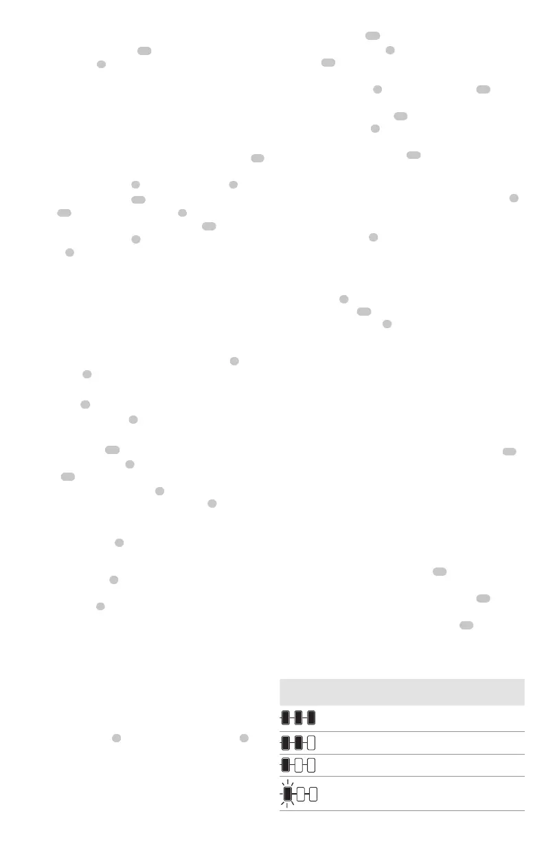
• The state of charge indicator LEDs
25
will illuminate,
indicating the percent of charge in the battery.
• When all three state of charge indicator LEDs
25
illuminate, the battery is fully charged.
• When one state of charge indicator LEDs
25
illuminates,
charge is low and then it will flash red when the battery
isdischarged. Remove thebattery and charge it.
State of Charge Indicator Status
LEVEL OF CHARGE
CHARGE INDICATOR
LED COLOR
100% - 75% Yellow
50% - 75% Yellow
10% - 50% Red
10% or less.
Low battery shutdown
Red and LED screen flashing.
LED Screen (Fig. F–I)
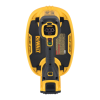
The DCE592 is equiped with a multicolor LED screen
6
.
The LED screen
6
displays units of pressure, state of battery
charge, and state of pressure lights.
Mode button
7
(Fig. A–F)
1. Press the mode button
7
to switch until the unit
measurement is set to PSI or bar.
Vacuum indicators
18
display green (Fig. F–I)
When the vacuum button
8
is activated, the four vacuum
indicators
18
will illuminate green.
1. Slide the on/off power switch
2
to the ON position.
TheDCE592 is now on, and the LED screen
6
display
shows 0PSI/bar and no lights.
2. After placing on clean surface of load to be lifted, press
the vacuum button
8
once. The vacuum pump will
activate and pressure will begin to build to -12 PSI
(-0.83bar). Four green lights illuminate in sequence
on the LED screen
6
as the pressure builds to
maximumlevel.
3. The LED screen
6
displays the pressure in units of bar or PSI
depending on the mode button. The vacuum pump
stops
running when the pressure reaches -12 PSI (-0.83bar) .
4. If vacuum pressure falls below -10.4 PSI (-0.72 bar), the
vacuum pump will automatically activate to restore
vacuum pressure to -12 PSI (-0.83bar).
5. If the material is too porous to achieve -12 PSI(-0.83bar)
vacuum pressure, the vacuum pump will runcontinuously.
WARNING: Use extreme caution when lifting in
this case because lifting capability is reduced.
6. The release button
9
and the on/off power switch
2
are electronically disabled while the vacuum pump
isenabled.
Connecting a Lifting Strap (Fig. A, P–S)
WARNING: Lifting straps used must be compliant
with ASME B30.9. Lifting Hooks must be
compliant with ASME B30.10. Rigging Hardware
must be compliant with ASME B30.26.
NOTE: User is responsible for sourcing proper lifting strap
19
accessory (sold separately) for use with your tool.
Locate the four strap latches
5
around the lifter body
4
.
1. Secure each of the clips
20
at the ends of the lifting
strap
19
into the four strap latches
5
.
NOTE: You must connect the lifting strap
19
to each
of the four strap latches
5
. Or just two of the strap
latches
5
depending upon the lifting orientation
(seeFig. P–S).
2. Ensure the lifting straps are not twisted or kinked
beforelifting.
3. Straps must be equal length and with equal tension on
them when lifting.
To Remove
1. Firmly pull the sun shade
17
up and away from the
motor housing
3
.




 To Next Page