32
ENGLISH
MAINTENANCE
Your power tool has been designed to operate over a long
period of time with a minimum of maintenance. Continuous
satisfactory operation depends upon proper tool care and
regularcleaning.
WARNING: To reduce the risk of serious personal
injury, turn tool off and disconnect battery pack
before making any adjustments or removing/
installing attachments or accessories. An accidental
start-up can causeinjury.
The charger and battery pack are notserviceable.
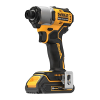
Usage (Fig. A)
CAUTION: Ensure fastener and/or system will withstand
the level of torque generated by the tool. Excessive torque
may cause breakage and possible personalinjury.
1. Place the accessory on the fastener head. Keep the tool
pointed straight at thefastener.
2. Press variable speed trigger switch
3
to start operation.
Release variable speed trigger switch to stop operation.
Always check torque with a torque wrench, as the fastening
torque is affected by many factors including the following:
- Voltage: Low voltage, due to a nearly discharged
battery, will reduce fasteningtorque.
- Accessory size: Failure to use the correct accessory size
will cause a reduction in fasteningtorque.
- Bolt size: Larger bolt diameters generally require
higher fastening torque. Fastening torque will also vary
according to length, grade, and torquecoefficient.
- Bolt: Ensure that all threads are free of rust and other
debris to allow proper fasteningtorque.
- Material: The type of material and surface finish of the
material will affect fasteningtorque.
- Fastening time: Longer fasten ing time results in
increased fastening torque. Using a longer fastening
time than recommended could cause the fasteners to
be overstressed, stripped ordamaged.
Modes 1and 2are optimized to match the installation speeds
of commonly used self‑drilling and tapping screws. Refer to the
impact driver manual and screw manufacturer instructions for
properinstallation.
NOTE: Select Mode 2when operating DeWALT IMPACT
CONNECTaccessories.
Specifications
Mode Application RPM
Mode 1 Low speed 0‑1800 forward
0‑1800 reverse
Mode 2 Medium speed 0‑2500 forward
0‑2500 reverse
Mode 3 High speed 0‑3800 forward
0‑3800 reverse
Mode 4 Flashlight mode
Worklight (Fig. A, C)
CAUTION: Do not stare into worklight. Serious eye
injury couldresult.
The worklight
8
comes with multiplesettings.
Pressing the worklight button
12
repeatedly will cycle
through low illumination for 20seconds, high illumination for
20seconds, high illumination for 20minutes, and off.
When the worklight icon is lit, the high illumination 20minute
LED mode isenabled.
NOTE: The worklight is for lighting the immediate work surface
and is not intended to be used as aflashlight.
Forward/Reverse Control Button (Fig. A)
A forward/reverse control button
4
determines the direction of
the tool and also serves as a lock‑offbutton.
To select forward rotation, release the trigger switch and
depress the forward/reverse control button on the right side of
thetool.
To select reverse, release the trigger switch and depress the
forward/reverse control button on the left side of thetool.
The centre position of the control button locks the tool in the off
position. When changing the position of the control button, be
sure the trigger isreleased.
NOTE: The first time the tool is run after changing the direction
of rotation, you may hear a click on start up. This is normal and
does not indicate aproblem.
Variable Speed Trigger Switch (Fig. A)
To turn the tool on, squeeze the trigger switch
3
. To turn the
tool off, release the trigger switch. Your tool is equipped with
a brake. The anvil will stop when the trigger switch is fully
released. The variable speed switch enables you to select the
best speed for a particular application. The more you squeeze
the trigger, the faster the tool will operate. For maximum tool
life, use variable speed only for starting holes orfasteners.
NOTE: Continuous use in variable speed range is not
recommended. It may damage the switch and should beavoided.
Proper Hand Position (Fig. E)
WARNING: To reduce the risk of serious personal injury,
ALWAYS use proper hand position as shown.
WARNING: To reduce the risk of serious personal
injury, ALWAYS hold securely in anticipation of a
suddenreaction.
Proper hand position requires one hand on the main
handle
11
.
before making any adjustments or removing/
installing attachments or accessories. An accidental
start-up can causeinjury.
Mode Selector (Fig. A, C)
Your tool is equipped with a mode selector
7
which allows you
to select one of three modes. Select the mode based on the
maximum speed/torque needed and control the speed of the
tool using the variable speed trigger
3
.
 Loading...