ENGLISH
6
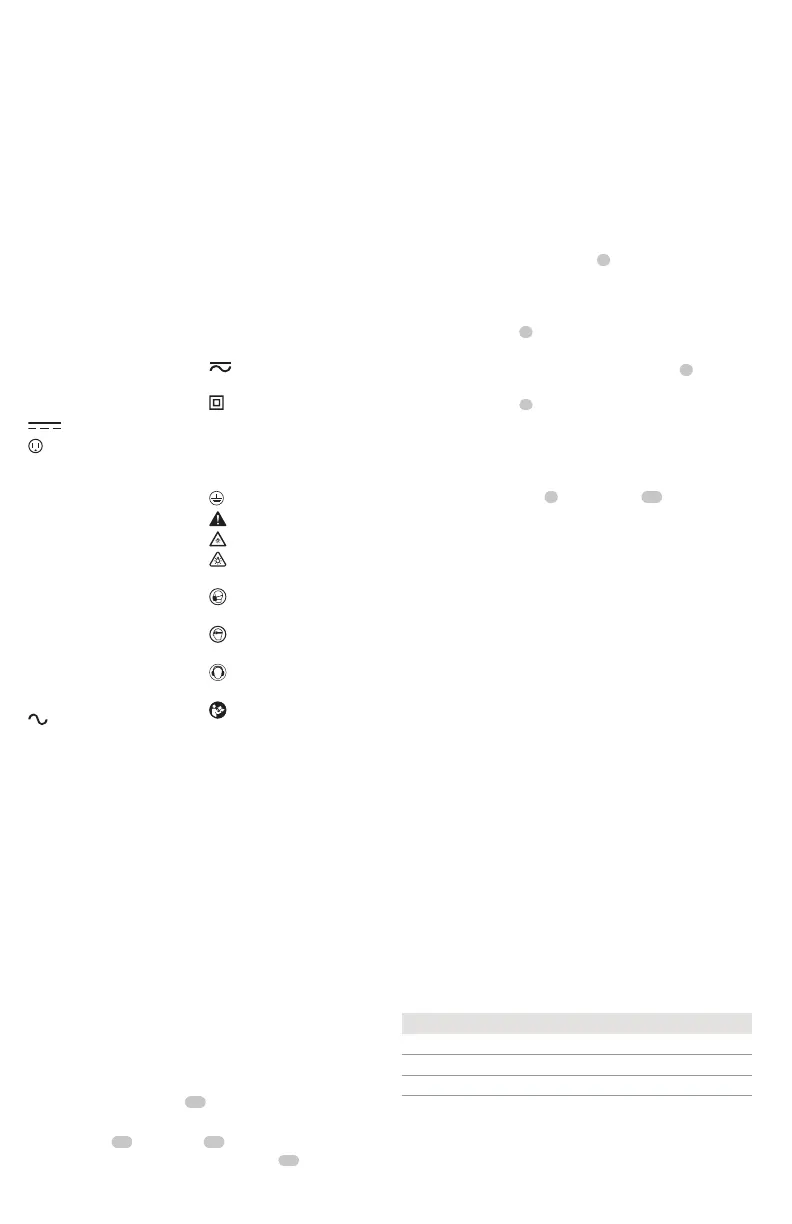
Precision Drive™ (Fig.A)
DCF801
In addition to normal impacting modes, this tool features
the Precision Drive™ mode which enables greater control
in lighter applications to avoid damage to materials or
fasteners. It is ideal for light applications such as cabinet
hinge screws or machine screws. Precision Drive™ mode will
work as a screwdriver in light applications, before hesitating
as the screw head reaches the workpiece, and then (if
required) start a slow controlled impact to ensure the head
ends perfectlyflush.
NOTE: This mode is for light duty screwdriving applications.
If the tool will not drive a fastener in Precision Drive™
mode, please select Lo Mode which will give the additional
powerrequired.
DCF801
Precision Drive™ mode Precision Drive™
Lo Mode Low Speed Impacting
Hi Mode High Speed Impacting
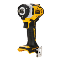
Precision Wrench™ (Fig. A)
DCF902
In addition to normal impacting modes, this tool features
the Precision Wrench™ mode which grants the user greater
OPERATION
WARNING: To reduce the risk of serious personal
injury, turn unit off and remove the battery pack
before making any adjustments or removing/installing
attachments or accessories. An accidental start-up can
causeinjury.
Belt Hook and Bit Clip (Fig. B)
Optional Accessory
WARNING: To reduce the risk of serious personal
injury, ONLY use the tool’s belt hook to hang the tool
from a work belt. DO NOT use the belt hook for tethering
or securing the tool to a person or object during use. DO NOT
suspend tool overhead or suspend objects from the belthook.
WARNING: To reduce the risk of serious personal
injury, ensure the screw holding the belt hook issecure.
IMPORTANT: When attaching or replacing the belt hook or
bit clip, use only the screw
12
that is provided. Be sure to
securely tighten thescrew.
The belt hook
11
and bit clip
13
can be attached to
either side of the tool using only the screw
12
provided, to
ASSEMBLY AND ADJUSTMENTS
WARNING: To reduce the risk of serious personal
injury, turn unit off and remove the battery pack
before making any adjustments or removing/installing
attachments or accessories. An accidental start-up can
causeinjury.
The label on your tool may include the following symbols. The
symbols and their definitions are asfollows:
V ......................... volts
Hz .......................hertz
min ..................... minutes
or DC ......direct current
...................... Class I Construction
(grounded)
…/min ..............per minute
BPM .................... beats per minute
IPM ..................... impacts per minute
RPM .................... revolutions per
minute
sfpm ................... surface feet per
minute
SPM .................... strokes per minute
OPM .................... oscillations per
minute
A ......................... amperes
W ........................watts
or AC ...........alternating current
or AC/DC .... alternating or
direct current
...................... Class II
Construction
(double insulated)
n
o
.......................no load speed
n .........................rated speed
......................earthing terminal
.....................safety alert symbol
.....................visible radiation
..................... avoid staring at
light
..................... wear respiratory
protection
..................... wear eye
protection
..................... wear hearing
protection
..................... read all
documentation
IPXX .................... IP symbol
Anvil with Hog Ring (Fig. A)
DCF902
To install an accessory on the hog ring anvil, firmly push
accessory onto the anvil
9
. The hog ring
10
compresses
to allow the accessory to slide on. After accessory is
installed, the hog ring applies pressure to help provide
accessoryretention.
To remove an accessory, grasp the accessory and firmly
pull it off.
Quick-Release Chuck (Fig.C)
DCF801
NOTE: The chuck accepts 1/4" (6.35 mm) hex accessories
and 1" (25.4 mm) bit tips only.
Place the forward/reverse button
4
in the lock-off
(center) position and remove battery pack before
changingaccessories.
To install an accessory, fully insert the accessory into the
quick-release chuck
7
. The accessory is locked into place
(Fig.C).
To remove an accessory, pull the chuck collar
8
away
from the front of the tool. Remove the accessory from the
quick-release chuck
7
(Fig.C).
other injury. Always use NIOSH/OSHA approved respiratory
protection appropriate for the dust exposure. Direct particles
away from face andbody.
WARNING: Always wear proper personal hearing
protection that conforms to ANSI S12.6 (S3.19) during
use. Under some conditions and duration of use, noise from
this product may contribute to hearingloss.
CAUTION: When not in use, place tool on its side
on a stable surface where it will not cause a tripping
or falling hazard. Some tools with large battery packs
will stand upright on the battery packbut may be easily
knockedover.
• Air vents often cover moving parts and should be
avoided. Loose clothes, jewelry or long hair can be caught in
movingparts.
accommodate left- or right- handed users. If the belt hook
or bit clip is not desired at all, they can be removed from
thetool.
To move the belt hook or bit clip, remove the screw that
holds it in place then reassemble on the opposite side. Be
sure to securely tighten thescrew.