29
ENGLISH
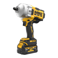
Variable Speed Trigger Switch (Fig.A)
To turn the tool on, squeeze the trigger switch
1
. To turn the
tool off, release the trigger switch. Your tool is equipped with
a brake. The anvil will stop when the trigger switch is fully
released. The variable speed switch enables you to select the
best speed for a particular application. The more you squeeze
the trigger, the faster the tool will operate. For maximum tool
life, use variable speed only for starting holes orfasteners.
NOTE: Continuous use in variable speed range is not
recommended. It may damage the switch and should beavoided.
OPERATION
Instructions for Use
WARNING: Always observe the safety instructions and
applicableregulations.
WARNING: To reduce the risk of serious personal
injury, turn tool off and disconnect battery pack
before making any adjustments or removing/
installing attachments or accessories. An accidental
start-up can causeinjury.
Place the switch in the locked off (centre) position or remove
battery pack before changingaccessories.
To install an accessory on the hog ring anvil, firmly push
accessory onto the anvil
3
. The hog ring
10
compresses to
allow the accessory to slide on. After accessory is installed, the
hog ring applies pressure to help provide accessoryretention.
To remove an accessory, grasp the accessory and firmly pull itoff.
Mode Selector (Fig.A, D)
Your tool is equipped with a mode selector
9
which allows you
to select one of three speeds or Precision Wrench™ mode. Select
the mode based on the maximum speed/torque needed and
control the speed of the tool using the variable speed trigger
switch
1
.
Precision Wrench™ (Fig.D)
In addition to normal impacting modes, this tool features the
Precision Wrench™ mode which grants the user greater control
in both fastening and loosening applications. When set in
forward, the tool will fasten at 1200RPM until impact begins.
The tool will then pause for 0.75 seconds before continuing
to impact at a rate of 1890IPM (DCF961)/ 2050 IPM (DCF964),
providing the user with greater control and reducing the chance
of overtightening or damagingmaterial.
When set in reverse, the tool will impact at a normal speed
and rate of 1890IPM (DCF961)/ 2050 IPM (DCF964). Upon
sensing that the fastener has broken free, the tool will cease
to impact and will reduce speed to help prevent “run-off” of
loosehardware.
Specifications
DCF961 DCF964
Mode Application RPM RPM
Precision
Wrench™ Mode
Precision
Wrench™
0–1200 forward 0–1200 forward
0–550 reverse 0–550 reverse
Low Mode Normal Impacting 0–440 forward 0–440 forward
0–1200 reverse 0–1200 reverse
Medium Mode Medium Impacting 0–800 forward 0–575 forward
0–1200 reverse 0–1200 reverse
High Mode* High Speed
Impacting
0–1200 forward 0–1200 forward
0–1200 reverse 0–1200 reverse
*After 4 seconds of impacting, the DCF961/DCF964 automatically increases
power to aid in loosening stubborn fasteners.
Forward/Reverse Control Button (Fig.A)
A forward/reverse control button
2
determines the direction of
the tool and also serves as a lock-offbutton.
To select forward rotation, release the trigger switch and
depress the for ward/re verse control button on the right side of
thetool.
To select reverse, release the trigger switch and depress the
forward/reverse control button on the left side of thetool.
The centre position of the control button locks the tool in the off
position. When changing the position of the control button, be
sure the trigger isreleased.
NOTE: The first time the tool is run after changing the direction
of rotation, you may hear a click on start-up. This is normal and
does not indicate aproblem.
Worklight (Fig.A, D)
The worklight
7
is activated when the variable speed trigger
1
is depressed. Pressing the worklight switch
8
repeatedly will
cycle through low illumination, high illumination, andoff.
NOTE: The worklight is for lighting the immediate work surface
and is not intended to be used as aflashlight.
Proper Hand Position (Fig.E)
WARNING: To reduce the risk of serious personal injury,
ALWAYS use proper hand position asshown.
WARNING: To reduce the risk of serious personal
injury, ALWAYS hold securely in anticipation of a
suddenreaction.
Proper hand position requires one hand on the main handle
8
.
Usage (Fig.A)
CAUTION: Ensure fastener and/or system will withstand
the level of torque generated by the tool. Excessive torque
may cause breakage and possible personalinjury.
1. Place the accessory on the fastener head. Keep the tool
pointed straight at thefastener.
2. Press variable speed trigger switch
1
to start operation.
Release variable speed trigger switch to stop operation.
Always check torque with a torque wrench, as the fastening
torque is affected by many factors including the following:
- Voltage: Low voltage, due to a nearly discharged
battery, will reduce fasteningtorque.
- Accessory size: Failure to use the correct accessory size
will cause a reduction in fasteningtorque.
 Loading...