ENGLISH
14
accessory. When servicing this tool, use only identical
replacementparts.
NOTICE: All the mechanical parts of the driver
replacment kit are shown for convenience and
verification ofinclusion.
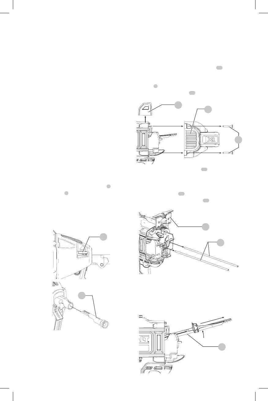
To change a worn driver
1. Using a T-20 Torx, loosen the four screws
18
on either
side of the unit. Refer to FigureM.
2. Remove the four screws and the removable top
stand
7
. Refer to FigureM.
3. Remove housing end cap
19
. Refer to FigureM.
Fig. M
7
19
18
4. Push up on the rear of the driver
20
until you hear a
click, then push the driver forward while holding it in
this position until it passes the upper bumper assembly.
Refer to FigureO.
5. Remove guide rods
21
. Refer to FigureO.
6. Remove upper bumper assembly
16
. Refer to FigureN.
Fig. N
21
16
7. Lift the rear of driver until at an angle and pull the driver
out. Refer to FigureO.
8. Replace driver and follow steps in reverse to reassemble
9. Ensure new driver slides smoothly through the gun
before fullreassembly.
Fig. O
20
Accessories
WARNING: Since accessories, other than those
offered by
, have not been tested with this
product, use of such accessories with this tool could be
hazardous. To reduce the risk of injury, only
recommended accessories should be used with
thisproduct.
DCN8901 Driver Blade Replacement Kit
DCN8902 Magnetic Stick-E Contact Trip
DCN8903 Stick-E Contact Trip
DCN8904 Standard Contact Trip
DCN8905 Pole Tool
DCN8906 Cordless Concrete Nailer 2-1/4" Magazine
DCN8902: Magnetic Stick-E Contact Trip
(Fig. L)
For some applications, using a Stick-E contact trip may
bedesirable.
WARNING: For your own safety, read the tool
instruction manual before using any accessory.
Failure to heed these warnings may result in personal
injury and serious damage to the tool and the
accessory. When servicing this tool, use only identical
replacementparts.
To Replace Contact Trip
1. Push down on the contact trip releaselever
5
.
2. Pull the contact trip
6
out of the nose of the tool.
3. Hold down the trip release lever.
4. With the contact trip alignment marker facing up, as
shown in Figure L, insert the contact trip fully into
thetoolnose.
5. Release thelever.
Fig. L
5
6
DCN8901 Driver Blade Replacement Kit
(Fig. M, N, O)
WARNING: For your own safety, read the tool
instruction manual before using any accessory.
Failure to heed these warnings may result in serious
personal injury and damage to the tool and the