ENGLISH
10
tool. This can seriously affect the life and performance
of thetool.
NOTE: The battery pack is not fully charged out of the
carton. Follow instructions outlined (refer to Charging
ABattery).
1. Read the Nailer Safety Warnings section of
thismanual.
2. Wear eye and earprotection.
3. Remove battery fromtool.
4. Ensure magazine is empty of allfastners.
5. Check for smooth and proper operation of contact
trip and pusher assemblies. Do not use tool if either
assembly is not functioning properly. NEVER use
a tool that has the contact trip restrained in the
actuatedposition.
6. Keep tool pointed away from yourself andothers.
7. Insert fully charged batterypack.
Using the Trigger Lock-off (Fig. F)
WARNING: To reduce the risk of serious personal
injury, do not keep trigger depressed when tool is not
in use. Keep the trigger lock-off switch LOCKED (Fig.F)
when the tool is not inuse.
WARNING: To reduce the risk of serious personal
injury, lock off trigger, disconnect battery pack
from tool and remove pins from magazine before
makingadjustments.
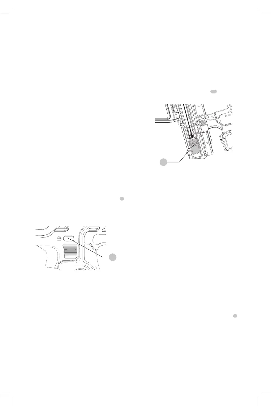
Each
nailer is equipped with a trigger lock-off
2
which when pushed to the right as shown in FigureF,
prevents the tool from firing a pin by locking the trigger and
bypassing power to themotor.
Fig. F
2
When the trigger lock-off is pressed to the left, the tool will
be fully operational. The trigger lock-off should always be
locked off whenever any adjustments are made or when
tool is not in immediateuse.
NOTICE: Do not store tool with battery pack installed.
To prevent damage to the pack and to ensure best
battery life, store battery packs out of the tool or
charger in a cool, drylocation.
Loading the Tool (Fig. G)
WARNING: Keep the tool pointed away from yourself
andothers.
WARNING: Never load pins with the contact trip or
triggeractivated.
WARNING: Always remove battery pack before
loading or unloadingpins.
CAUTION: Keep fingers clear of pusher latch track to
preventinjury.
WARNING: The trigger lock-off should always be
engaged whenever any adjustments are made or
when tool is not inuse.
WARNING: Fasteners used to install metal connectors
must meet the requirements of the applicable building
codes and must be installed in compliance with code
requirements and metal connector hardware supplier
specifications. Failure to properly install connectors
may result in structuralfailures.
1. Turn the nailer upsidedown.
2. Slide the spring-loaded pusher latch
15
to the base of
the magazine to lock it intoplace.
Fig. G
15
3. Drop pin strips into the loading slot of the magazine,
making sure the pin heads align correctly with the slot
opening. (Refer to Pin Specifications to determine
compatible size.)
4. Keeping fingers clear of the track, close the magazine by
releasing the pusher latch. Carefully allow the latch to
slide forward and engage the pinstrip.
Unloading the Tool
WARNING: The trigger lock-off should always be
locked off whenever any adjustments are made or
when tool is not inuse.
1. Slide the spring-loaded pusher latch to the base of the
magazine to lock it intoplace.
2. Tip the tool up until the fastener strip slides freely out of
themagazine.
3. With battery removed, check the nosepiece to verify
there are no pinsremaining.
NOTE: The tool is equipped with a magnet in the nose
area for improved tool performance. When unloading,
always verify that the small sticks of pins are not held to the
magnetized nosepiece.
Power Setting Summary (Fig. H, I)
This nailer is equipped with a power selection switch
3
to
adjust the tool when driving into differentmaterials.
Power setting 1: Softer materials (low strength concrete/
cinder block)
Power setting 2: Medium hardness materials (High strength
concrete)
Power setting 3: Hard materials (Structural Steel)
In the event pins are not driving to depth in power setting1,
you may have to switch to power 2 or 3 for additional
drivingpower.