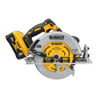
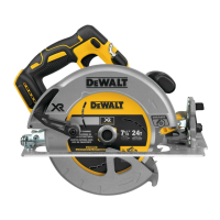
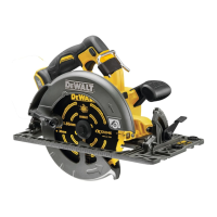
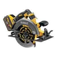
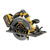
battery packs include a fuel gauge which
consists of three green LED lights that indicate the level of
charge remaining in the batterypack.
To actuate the fuel gauge, press and hold the fuel gauge button
20
. A combination of the three green LED lights will illuminate
designating the level of charge left. When the level of charge
in the battery is below the usable limit, the fuel gauge will not
illuminate and the battery will need to berecharged.
NOTE: The fuel gauge is only an indication of the charge left on
the battery pack. It does not indicate tool functionality and is
subject to variation based on product components, temperature
and end-userapplication.
Bevel Adjustment (Fig. A)
The bevel angle can be adjusted between 0° and 47°.
1. Loosen the bevel adjustment knobs
7
.
2. Set the bevel angle by tilting the saw shoe
4
until the mark
indicates the desired angle on the bevel scale
6
.
3. Tighten the bevel adjustment knobs
7
.
Changing the Saw Blade (Fig. A–C)
NOTE: It is not necessary to remove the outer blade cover
23
to change the blade.
1. Remove the battery pack.
2. Press the spindle lock button
12
.
3. Press the plunge saw down until it stops (blade
changeposition).
4. Turn the spindle lock lever
13
clockwise until it stops.
5. Hold the spindle lock lever
13
down and using the hex
wrench found in the front handle
11
, rotate the blade until
the lock position is found.
NOTE: The blade
10
is now locked and cannot be turned by
hand.
6. Use the hex wrench to turn the blade clamping screw
24
anti-clockwise to remove.
7. Remove the outer flange
25
and used blade
10
. Place the
new blade on the inner flange
26
.
8. Replace the outer flange
25
and blade clamping screw
24
.
Turn the screw clockwise by hand.
NOTE: The direction of rotation of the saw blade and the
rotation of the plunge saw MUST be the same.
9. Tighten the blade clamping screw firmly using the
hexwrench.
10. Release and turn the spindle lock lever
13
anti-clockwise
until it stops.
11. Move the plunge saw back to top position.
12. Push the plunge trigger
1
forward, to take the saw out of
blade change mode.
Adjusting the Riving Knife (Fig. A–C)
For the correct adjustment of the riving knife
21
, refer to
FigureC. Adjust the clearance of the riving knife after changing
the saw blade or whenever necessary.
1. Follow Changing the Saw Blade steps 1–5.
2. Loosen the riving knife adjustment screw
22
with a hex
wrench and set the riving knife as shown in FigureC.
3. Tighten the riving knife adjustment screw
22
.
4. Turn the spindle lock lever
13
anti-clockwise until it stops.
5. Move the plunge saw back to top position.
6. Push the plunge trigger
1
forward, to take the saw out of
blade change mode.
Depth of Cut Adjustment (Fig. D)
The cutting depth can be set at 0–59 mm without guide rail
attached; with the guide rail attached: 0–55 mm.
1. Loosen the depth adjustment knob
8
and move the
pointer to obtain the correct depth of cut.
2. Tighten the depth adjustment knob
8
.
NOTE: For optimal results, allow the saw blade to protrude from
the workpiece by about 3 mm (Fig.D).
OPERATION
Instructions for Use
WARNING: Always observe the safety instructions and
applicableregulations.
WARNING: To reduce the risk of serious personal
injury, turn tool off and disconnect battery pack
before making any adjustments or removing/
installing attachments or accessories. An accidental
start-up can causeinjury.
Proper Hand Position (Fig. E)
WARNING: To reduce the risk of serious personal injury,
ALWAYS use proper hand position asshown.
WARNING: To reduce the risk of serious personal
injury, ALWAYS hold securely in anticipation of a
suddenreaction.
Proper hand position requires one hand on the front handle
11
,
with the other hand on the main handle
3
.
Switching On and Off (Fig. A)
Press the on/off switch
2
to turn the plunge saw on.
Guiding the Tool (Fig. A, E, F)
WARNING:
• ALWAYS secure the workpiece in such a manner that
it cannot move while sawing.
• ALWAYS push the machine forward. NEVER pull the
machine backward towards you.
• ALWAYS use the plunge saw with both hands. Put
one hand on the main handle
3
and the second hand
on the front handle
11
as shown in FigureE.
• ALWAYS use the clamp to hold the rail to the
workpiece.
• Use proper hand position to guide the saw properly.
• The cutting indicator
27
displays the cutting line for 0° and
47° cuts (without guide rail).
 Loading...
