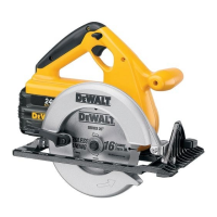
17
1. TURN OFF THE TOOL AND
REMOVE THE BATTERY PACK.
2. Loosen (counterclockwise) the
quadrant knob and tilt shoe to the
desired angle by aligning the pointer
with the desired angle mark.
3. Retighten knob firmly (clockwise).
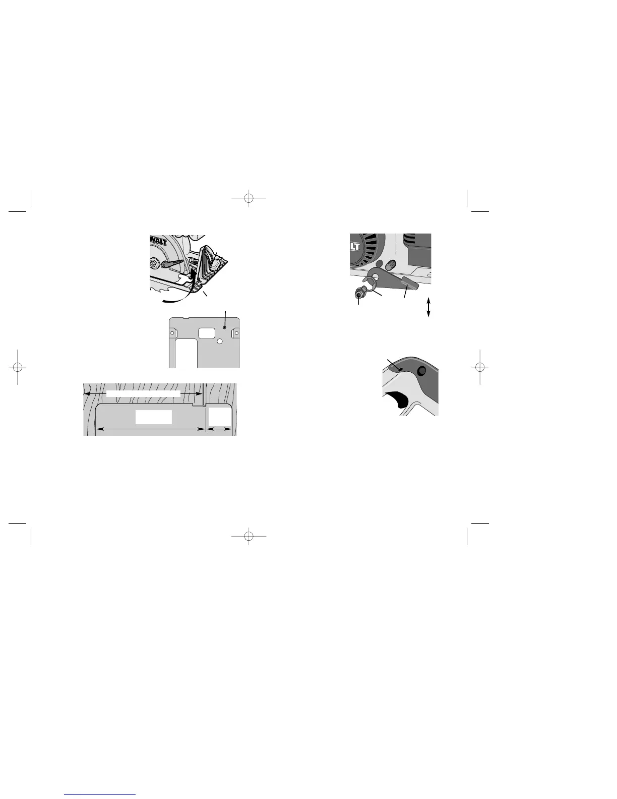
Adjusting for 90° Cuts (Fig. E9)
1. TURN OFF THE TOOL AND
REMOVE THE BATTERY PACK.
2. Adjust the saw to 0˚ bevel.
3. Retract blade guard. Place saw on blade
side.
4. Loosen bevel adjustment knob. Place a
square against the blade and shoe to adjust
the 90˚ setting.
5. Run in the adjustment set screw (A) so that
the shoe will stop at the proper angle.
Kerf Indicator (Fig. E10)
The front of the saw shoe has a kerf indicator
(Figure E10) for vertical and bevel cutting. This indicator enables you to guide the
saw along cutting lines pencilled on the material being cut. At 0˚ bevel, the kerf
indicator lines up with the right (outer) side of the saw blade. At 45˚ bevel the kerf
indicator lines up with the left (inner) side of the saw blade. Guide along the pencilled
cutting line so that the kerf falls into the waste or surplus material. Figure E10 shows
the dimensions of the shoe. The right dimension 38mm (1-1/2”).
Adjusting Depth Adjustment Lever (Fig. E11)
It may be desirable to adjust the Depth
Adjustment Lever. (It will sometimes
swing below the bottom of the shoe
before tightening or loosening
completely.) To adjust lever, follow the
steps below.
1. TURN OFF THE TOOL AND
REMOVE THE BATTERY
PACK.
2. Using a small screwdriver, pry off
the lock ring.
3. Remove the lever and rotate it in
the desired direction about 1/8
revolution. (More or less as
necessary.)
4. Reinstall the lever and insert the lock ring with concave side against lever to
hold it in place.
Operation Switch
Release lock-off by pressing button Fig. E12 (A). Pull
the trigger switch to turn the motor ON. Releasing
the trigger turns the motor OFF. Releasing the
trigger also automatically actuates lock off button.
NOTE: This tool has no provision to lock the
switch in the ON position, and should never be
locked in the ON position by any other means.
A
B
E8
E9
E10
A
127mm (5”)
38mm
(1-1/2”)
Desired width of stock
E11
E12
Lock
Nut
Lock
RING
LEVER
LOOSEN
TIGHTEN
A