ENGLISH
4
DATE CODE POSITION
The Date Code, which also includes the year of
manufacture, is printed into the housing surface that
forms the mounting joint between tool and battery.
Example:
2014 XX XX
Year of Manufacture
Package Contents
The package contains:
1 Rotary drill
1 Side handle
1 spade handle
1 Instruction manual
• Check for damage to the tool, parts or
accessories which may have occurred during
transport.
• Take the time to thoroughly read and
understand this manual prior to operation.
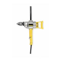
Description
Your professional DEWALT rotary drill DW130V has
been designed for heavy duty rotary drilling, thread
tapping and mixing.
1 On/off-switch
2. Forward/reverse slider
3. Keyed chuck
4. Side handle
5. spade handle
SAVE THESE INSTRUCTIONS FOR
FUTURE USE
Motor
Be sure your power supply agrees with the
nameplate marking. Voltage decrease of more than
10% will cause loss of power and overheating.
DeWALT tools are factory tested; if this tool does not
operate, check power supply.
Assembly and adjustments
WARNING: To reduce the risk of
injury, turn unit off and disconnect
it from power source before
installing and removing accessories,
before adjusting or when making
repairs. An accidental start-up can
cause injury.
Spade Handle Assembly (Fig. 1)
This spade handle can be attached either
horizontally or vertically. Place the handle into the
locating boss on the back of the drill and assemble
with holding knob.
Side Handle (Fig. 1)
WARNING: To reduce the risk of
personal injury, always operate the tool
with the side handle properly installed.
Failure to do so may result in the side
handle slipping during tool operation
and subsequent loss of control. Hold
tool with both hands to maximize
control.
The side handle can be placed in either side of
the drill or the top of the drill according to operator
preference and available working clearance. The
spade handle can be temporarily removed if working
clearance at rear of tool is limited. Always replace
spade handle when possible.
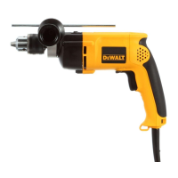
Switch (Fig. 2)
To start the drill, depress the trigger switch; to stop
the drill, release the trigger.
A variable speed trigger switch (A) permits speed
control—the farther the trigger is depressed, the
higher the speed of the drill.
NOTE: Use lower speeds for starting holes without
a center punch, drilling in metal or plastics, driving
screws or drilling ceramics. Higher speeds are better
for drilling wood and composition boards and using
abrasive and polishing accessories.
The reversing lever (B) is used for withdrawing bits
from tight holes and removing screws. It is located
above the trigger switch. To reverse the motor,
release the trigger switch FIRST and then push the
lever to the right. After any reversing operations,
return lever to forward position.
The locking feature (C) is for use when the drill is
mounted in a drill stand or otherwise firmly held…
NOT BY HAND.
Do not lock the switch “ON” when drilling by hand
so that you can instantly release the trigger switch if
the bit binds in the hole.
Be sure to release the switch locking button
before disconnecting the plug from the power