Switching On and Off
To switch the tool on, squeeze the trigger switch (A).
For continuous operation, squeeze the trigger switch then depress
the lock-on button (B). Once lock-on button is depressed, release the
trigger switch.
To switch the tool off, release the trigger switch. To switch the tool
off, when in continuous operation, squeeze the trigger and the lock
will disengage.
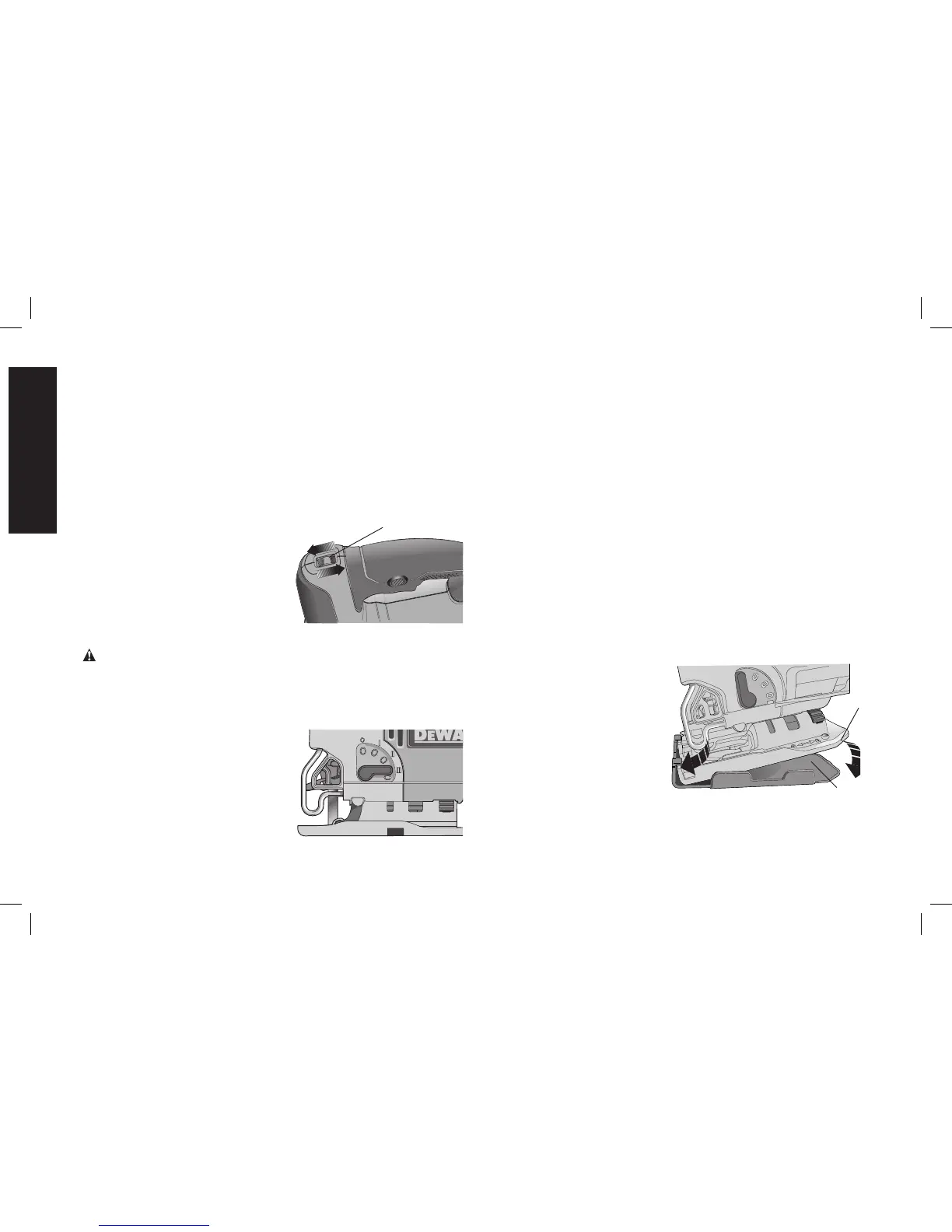
Variable Speed Control (Fig. 4)
A speed control wheel (H) is
FIG. 4
H
located on the top of the saw. The
speed increases as the wheel is
turned from a low speed setting of
1 to a high speed setting of 7.
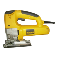
Cutting Action –
Orbital or Straight
(Fig. 5)
WARNING: Check that the tool is not locked ON before connecting
it to a power supply. If the trigger switch is locked on when the tool is
connected to the power supply, it will start immediately. Damage to
your tool or personal injury may result.
This jig saw is equipped with
FIG. 5
four cutting actions, three orbital
and one straight. Orbital action
has a more aggressive blade
motion and is designed for cutting
in soft materials like wood or
plastic. Orbital action provides a
faster cut, but with a less smooth
cut across the material. In orbital
action, the blade moves forward during the cutting stroke in addition
to the up and down motion.
NOTE: Metal or hardwoods should never be cut in orbital action.
TO ADJUST THE CUTTING ACTION
1. Move the cutting action lever (I) between the four cutting
positions: 0, 1, 2, and 3.
2. Position 0 is straight cutting.
3. Positions 1, 2, and 3 are orbital cutting.
The aggressiveness of the cut increases as the lever is adjusted from
one to three, with three being the most aggressive cut.
LED Light
The jig saw is equipped with a light which projects on the cutting path.
The light will come on when the trigger switch is depressed and will
go off when the trigger switch is released.
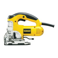
Removable Shoe Sleeve (Fig. 6)
The non-marring shoe sleeve (E) should be used when cutting
surfaces that scratch easily, such as laminate, veneer, or paint. It can
also be used to protect the shoe surface during transportation and
storage.
To attach shoe sleeve, place
FIG. 6
E
F
the front of the shoe (F) into
the front of the shoe sleeve
(E) and lower the jig saw as
shown in Figure 6. The shoe
sleeve will click securely onto
the rear of the shoe.
To remove shoe sleeve,
grasp the sleeve from the
bottom at the two rear tabs
and pull down and away from
the shoe.