SAVE THESE INSTRUCTIONS FOR FUTURE USE
Motor
Be sure your power supply agrees with the nameplate marking. Voltage decrease of more than
10% will cause loss of power and overheating. D
EWALT tools are factory tested; if this tool does
not operate, check power supply.
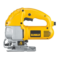
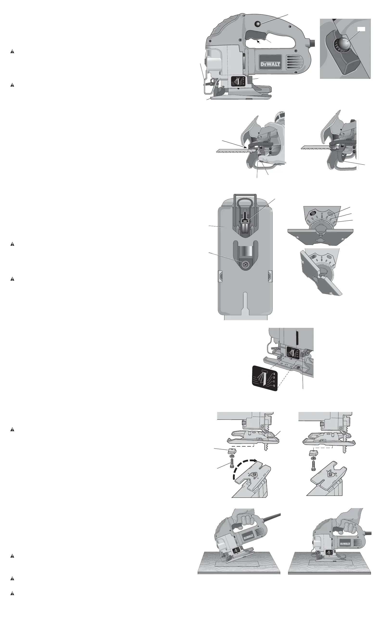
COMPONENTS (Fig. 1, 2)
WARNING: Never modify the power tool or any part of it. Damage or personal injury could
result.
A. Trigger switch D. Keyless blade lever
B. Lock button E. Shoe
C. Speed control dial
OPERATION
WARNING: To reduce the risk of injury, turn unit off and disconnect it from power
source before installing and removing accessories, before adjusting or when making
repairs. An accidental start-up can cause injury.
Trigger Switch (Fig. 1)
To start the jig saw, squeeze the trigger switch (A).
To slow and stop the jig saw, release the trigger switch.
For continuous operation, squeeze the trigger switch then depress the lock button (B). Once
lock button is depressed, release the trigger switch.
To release from continuous operation, squeeze the trigger and the lock will disengage.
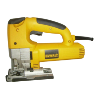
Variable Speed Switch (Fig. 1, 2)
The variable speed is controlled in two ways: speed control dial (C) and the trigger switch (A).
SPEED CONTROL DIAL
By rotating the speed control dial (C) in either direction, the maximum speed or strokes-per-
minute at which the blade will cut is adjusted. The speed control dial adjusts the speed that the
blade will cut from approximately 500 SPM to approximately 3,100 SPM.
TRIGGER SWITCH
As the trigger switch is pressed in, the strokes-per-minute continue to increase, but not to exceed
the maximum setting on the speed control dial. As the trigger is released, the blade strokes-per-
minute reduce.
Blade Installation and Removal (Fig. 3)
TO INSTALL A BLADE
1. Lift the keyless blade lever (D).
2. Insert the blade into the clamp mechanism (F) while guiding the back of the blade into the
groove of the guide rollers (G).
3. The shank should be completely inside the clamp mechanism as shown in Figure 4.
4. Release the keyless blade lever.
TO REMOVE A BLADE
1. Lift the keyless blade lever (D).
2. With a slight shake the blade will drop out.
CAUTION: Do not touch used blades, they may be hot. Personal injury may result.
Bevel Cutting Adjustment (Fig. 5)
Bevel cuts may be made at any angle between 0° and 45°. The shoe is adjusted by loosening
the screw (H) on the bottom of the tool and rotating the shoe to the desired angle. After setting
the shoe, tighten the screw firmly and use saw in the normal manner.
Cutting Action – Orbital or Straight (Fig. 6)
CAUTION: Check that the tool is not locked ON before connecting it to a power supply.
If the trigger switch is locked ON when the tool is connected to the power supply, it will start
immediately. Damage to your tool or personal injury may result.
This jig saw is equipped with four cutting actions, three orbital and one straight. Orbital action
has a more aggressive blade motion and is designed for cutting in soft materials like wood or
plastic. Orbital action provides a faster cut, but with a rougher cut across the material. In orbital
action, the blade moves forward during the cutting stroke in addition to the up and down motion.
NOTE: Metal or hardwoods should never be cut in orbital action.
To adjust the cutting action, move the cutting action lever (I) between the four cutting
positions: 0, 1, 2, and 3. Position 0 is straight cutting. Positions 1, 2, and 3 are orbital cutting.
The aggressiveness of the cut increase as the lever is adjusted from one to three, with three being
the most aggressive cut.
Adjustment For 90° Cuts
1. The 0° mark on the quadrant plate should line up with mark on shoe.
2. If adjustment is necessary, loosen screw on quadrant plate and adjust as necessary. Place
a right angle against the blade and the shoe and adjust the shoe to 90°.
Anti-Splintering (Fig. 7)
This jig saw has a special double-ended shoe with a wide opening at one end for general
cutting and bevel cutting and a very narrow slot at the other end for use only with hollow
ground blades.This narrow slot acts as an anti-splintering device (J) particularly useful when
cutting plywood.
Reversing Shoe Position (Fig. 7)
To reverse the shoe position remove the screw (H) from the bottom of the tool, as shown in
Figure7, and remove the shoe from the jig saw. [Be careful to note the position of the clamp
(K). This clamp must be re-installed the same way or the shoe will not fit properly.] Turn the shoe
around and re-install noting carefully that, when the slot is forward, the screw goes through the
hole in the shoe and when the wide opening is forward, the screw passes through the slot in
the shoe.
Cutting
WARNING: The jig saw should not be operated with the shoe removed or serious personal
injury may result.
POCKET CUTTING (FIG. 8, 9)
A pocket cut is an easy method of making an inside cut. The saw can be inserted directly into a
panel or board without first drilling a lead or pilot hole. In pocket cutting, measure the surface to
be cut and mark clearly with a pencil. Next tip the saw forward until the front end of the shoe sits
firmly on the work surface and the blade clears the work through its full stroke. Switch the tool on
and allow it to attain maximum speed. Grip the saw firmly and lower the back edge of tool slowly
until the blade reaches its complete depth. Hold the shoe flat against the wood and begin cutting.
Do not remove blade from cut while it is still moving. Blade must come to a complete stop.
WOOD CUTTING
Support the workpiece adequately at all times. Use the higher speed setting for cutting wood.
Do not attempt to turn the tool on when blade is against material to be cut. This could stall the
motor. Place the front of shoe on the material to be cut and hold the jig saw shoe firmly against
the wood while cutting. Don’t force the tool; let the blade cut at its own speed. When the cut is
complete, turn the jig saw off. Let blade come to a complete stop and then lay the saw aside
before loosening the work.
METAL CUTTING
In cutting thin gauge sheet metals, it is best to clamp wood to the bottom of sheet metal; this
will insure a clean cut without the risk of vibration or tearing of metal. Always remember to use a
finer blade for ferrous metals (for those that have a high iron content); and use a coarser blade for
non-ferrous metals (those that do not have an iron content). Use a high speed setting for cutting
soft metals (aluminum, copper, brass, mild steel, galvanized pipe, conduit sheet metal, etc.). Use
lower speed to cut plastics, tile, laminate, hard metals, and cast iron.
MAINTENANCE
WARNING: To reduce the risk of injury, turn unit off and disconnect it from power
source before installing and removing accessories, before adjusting or when making
repairs. An accidental start-up can cause injury.
Cleaning
WARNING: Blow dirt and dust out of all air vents with clean, dry air at least once a week. To
minimize the risk of eye injury, always wear ANSI Z87.1 approved eye protection when performing
this.
WARNING: Never use solvents or other harsh chemicals for cleaning the non-metallic parts
of the tool. These chemicals may weaken the plastic materials used in these parts. Use a cloth
dampened only with water and mild soap. Never let any liquid get inside the tool; never immerse
any part of the tool into a liquid.
FIG. 2
C
FIG. 6
I
FIG. 5
15°
30°
45°
FIG. 8
FIG. 9
FIG. 1 B
A
I
C
D
E
FIG. 3
FIG. 7
FIG. 4
J
G
F
D
D
F
H
H
K
E
Learn more about power tools on our website.
Lubrication
NOTE: NEVER spray or in an
y other way apply lubricants or cleaning solvents inside the tool.
This can seriously affect the life and performance of the tool.
DEWALT tools are properly lubricated at the factory and are ready for use. However, it
is recommended that, once a year, you take or send the tool to a certified service center
for a thorough cleaning and inspection.
 Loading...