English
4
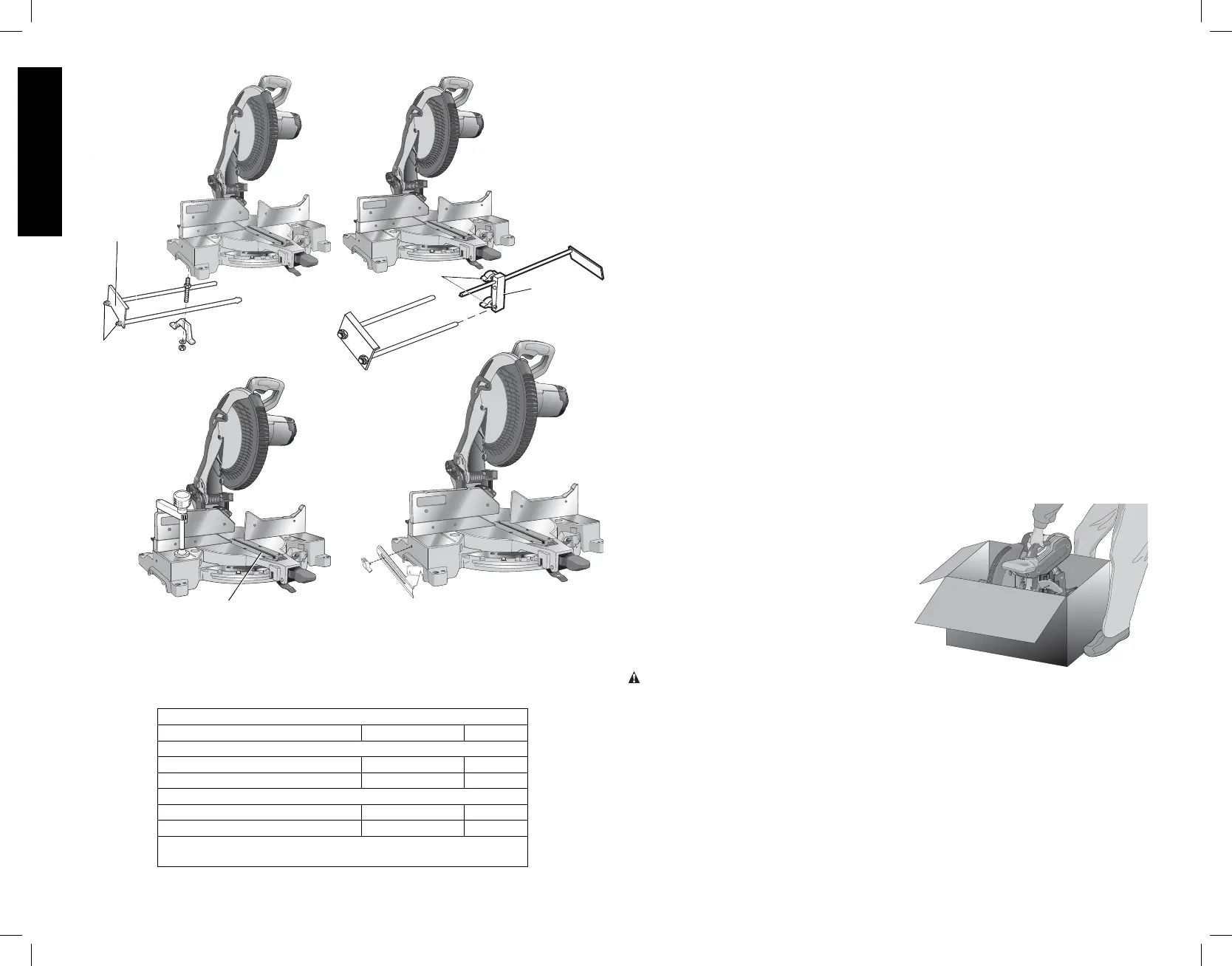
DW7080
END
PLATE
LOCK
NUTS
DW7084
DW7082
FIG. 1
DW7051
KNOBS
BRACKET
DW7055
SAW BLADES: ALWAYS USE 12" (305 mm) SAW BLADES WITH 1" (25.4 mm) ARBOR
HOLES. SPEED RATING MUST BE AT LEAST 4800 RPM. Never use a smaller diameter
blade. It will not be guarded properly. Use crosscut blades only! Do not use blades designed
for ripping, combination blades or blades with hook angles in excess of 7˚.
BLADE DESCRIPTIONS
APPLICATION DIAMETER TEETH
Construction Saw Blades (thin kerf with anti-stick rim)
General Purpose 12" (305 mm) 40
Fine Crosscuts 12" (305 mm) 60
Woodworking Saw Blades (provide smooth, clean cuts)
Fine crosscuts 12" (305 mm) 80
Non-ferrous metals 12" (305 mm) 96
NOTE: For cutting non-ferrous metals, use only saw blades with
TCG teeth designed for this purpose.
Unpacking Your Saw
Check the contents of your miter saw carton to make sure that you have received all parts. In
addition to this instruction manual, the carton should contain:
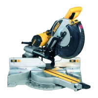
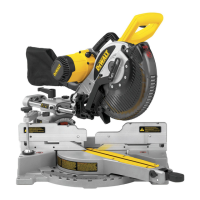
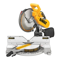
• One No. DW715 miter saw.
• One D
EWALT 12" (305 mm) dia. saw blade
• One blade wrench in wrench pocket shown in Figure 2.
• One DW7053 dustbag (some models).
Specifi cations
CAPACITY OF CUT
50° miter left and right
48° bevel left, 3° bevel right
0° miter
Max. Height 3.5" (89 mm) Result Width 6.5" (165 mm)
Max. Width 7.7" (196 mm) Result Height 2.6" (66 mm)
45° miter
Max. Height 3.5" (89 mm) Result Width 4.7" (120 mm)
Max. Width 5.5" (140 mm) Result Height 2.6" (66 mm)
45° bevel - Left
Max. Height 2.3" (58 mm) Result Width 6.7" (170 mm)
Max. Width 7.7" (196 mm) Result Height 1.7" (43 mm)
DRIVE
120 Volt Motor
1600 Watts (max in) 15 Amp Motor
4000 RPM Cut Helical Gears
Roller Bearings Carbide Blade
Automatic Electric Brake
Familiarization
Your miter saw is fully assembled in the carton.
FIG. 1A
Open the box and lift the saw out by the
convenient carry ing handle, as shown in
Figure 1A. Place the saw on a smooth, flat
surface such as a workbench or a strong table.
Examine Figure 2 to become familiar with
the saw and its various parts. The section on
adjus tments will refer to these terms and you
must know what and where the parts are.
CAUTION: Pinch Hazard. To reduce the risk of injury, keep thumb underneath the handle
when pulling the handle down. The lower guard will move up as the handle is pulled down
which could cause pinching. The handle is placed close to the guard for special cuts.
Press down lightly on the operating handle and pull out the lock down pin, as shown in Figure 2.
Gently release the downward pressure and hold the arm allowing it to rise to its full height. Use
the lock down pin when carrying the saw from one place to another. Always use the carrying
handle to transport the saw or the hand indentations shown in Figure 2 and 4.
Bench Mounting
Holes are provided in all four feet to facilitate bench mounting, as shown in Figure 2. (Two
different sized holes are provided to accommodate different sizes of screws. Use either hole,
it is not necessary to use both.) Always mount your saw firmly to a stable surface to prevent
movement. To enhance the tool’s portability, it can be mounted to a piece of 1/2" (12.7 mm)