ENGLISH
24
wash exposed areas with soap and water. Allowing
dust to get into your mouth, eyes, or lay on the skin may
promote absorption of harmfulchemicals.
WARNING: Use of this tool can generate and/
or disperse dust, which may cause serious and
permanent respiratory or other injury. Always use
NIOSH/OSHA approved respiratory protection
appropriate for the dust exposure. Direct particles
away from face andbody.
WARNING: Always wear proper personal hearing
protection that conforms to ANSI S12.6 (S3.19)
during use. Under some conditions and duration
of use, noise from this product may contribute to
hearingloss.
• Air vents often cover moving parts and should be
avoided. Loose clothes, jewelry or long hair can be
caught in movingparts.
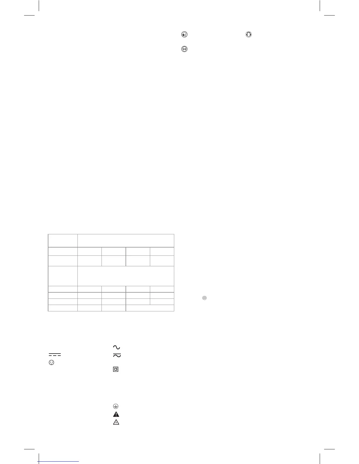
• An extension cord must have adequate wire size
for safety. The smaller the gauge number of the wire,
the greater the capacity of the cable, that is, 16 gauge
has more capacity than 18 gauge. An undersized cord
will cause a drop in line voltage resulting in loss of power
and overheating. When using more than one extension
to make up the total length, be sure each individual
extension contains at least the minimum wire size. The
following table shows the correct size to use depending on
cord length and nameplate ampere rating. If in doubt, use
the next heavier gauge. The lower the gauge number, the
heavier thecord.
Voltage
(Volts)
Total length of cord in meters (m)
120–127V 0–7 7–15 15–30 30–50
220–240V 0–15 15–30 30–60 60–100
Rated
Ampere
Range
Minimal cross-sectional area of the
cord in meters (mm
2
)
0–6A 1.0 1.5 1.5 2.5
6–10A 1.0 1.5 2.5 4.0
10–12A 1.5 1.5 2.5 4.0
12–16A 2.5 4.0 Not Recommended
The label on your tool may include the following symbols. The
symbols and their definitions are asfollows:
V ......................... volts
Hz .......................hertz
min ..................... minutes
or DC ......direct current
...................... Class I Construction
(grounded)
…/min ..............per minute
BPM ....................beats per minute
IPM ..................... impacts per minute
RPM .................... revolutions per
minute
sfpm ................... surface feet per
minute
SPM .................... strokes per minute
A ......................... amperes
W ........................watts
or AC ...........alternating current
or AC/DC .... alternating or
direct current
...................... Class II
Construction
(double insulated)
n
o
........................no load speed
n .........................rated speed
......................earthing terminal
.....................safety alert symbol
.....................visible radiation
..................... wear respiratory
protection
..................... wear eye
protection
..................... wear hearing
protection
SAVE THESE INSTRUCTIONS FOR
FUTURE USE
Motor
Be sure your power supply agrees with the nameplate
marking. Voltage decrease of more than 10% will cause loss
of power and overheating.
DW733 thickness planer has been designed
for professional cutting of wood. It performs planing
operations accurately and safely.
DO NOT use under wet conditions or in presence of
flammable liquids orgases.
This thickness planer is a professional power tool.
DO NOT let children come into contact with the tool.
Supervision is required when inexperienced operators use
thistool.
ASSEMBLY AND ADJUSTMENTS
WARNING: To reduce the risk of serious personal
injury, turn unit off and disconnect it from
power source before making any adjustments or
removing/installing attachments or accessories.
An accidental start-up can causeinjury.
Bench Mounting (Fig. B)
• Holes
6
are provided in all four feet to facilitate bench
mounting. Two different sized holes are provided to
accommodate different sizes of bolts. Use either hole;
it is not necessary to use both. Always mount your
machine firmly to prevent movement. To enhance
portability, the tool can be mounted to a piece of
12.5 mm or thicker plywood which can then be
clamped to your work support or moved to other job
sites andreclamped.
• When mounting your machine to a piece of plywood,
make sure that the mounting screws do not protrude
from the bottom of the wood. The plywood must sit
flush on the work support.
• To prevent binding and inaccuracy, be sure the
mounting surface is not warped or otherwise uneven.
WARNING: The machine must be level and stable at
all times.

 Loading...