7
ENGLISH
WARNING: Follow the fitting instructions supplied with good quality plugs.
Recommended fuse: 13A.
Using an Extension Cable
If an extension cable is required, use an approved 3–core extension cable suitable for the
power input of this tool (see Technical Data).The minimum conductor size is 1.5 mm
2
; the
maximum length is 30m.
When using a cable reel, always unwind the cablecompletely.
Package Contents
The package contains:
1 Thickness planer
1 Open‑ended key (8/10 mm)
2 Hex keys
1 Blade setting gauge
1 Dust extraction adaptor
1 Push stick
1 Instruction manual
Markings on Tool
The following pictograms are shown on the tool:
Read instruction manual beforeuse.
Wear earprotection.
Wear eyeprotection.
Direction of workflow
Keep hands away fromblade.
Carriage head lock
Material removal gauge
315mm
Max. cutting width 315mm
Turning direction of cutter block
Date Code Position (Fig.A1)
The date code
42
, which also includes the year of manufacture, is printed into thehousing.
Example:
2021XX XX
Year of Manufacture
Description (Fig.A1, A2)
WARNING: Never modify the power tool or any part of it. Damage or personal injury
couldresult.
Fig. A1
1
ON/OFF switch
2
Head lock lever
3
Depth adjustment handle
4
Carrying handle
5
Rear table extension
6
Mounting holes
7
Handholds
8
Depth adjustment scale
9
Material removal scale
10
Front table extension
11
Push stick
Fig. A2
12
Cord wrap
13
Tool tray
14
Dust extraction adaptor
15
Depth stop
16
Base
Intended Use
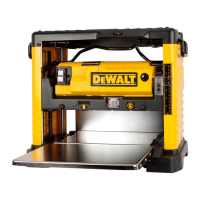
Your
DW733 thickness planer has been designed for professional cutting of wood. It
performs planing operations accurately andsafely.
With the thickness planer you can plane debarked, rectangular sawn timber of all kinds to the
desired width and thickness. The thickness planer was specially designed for planing solid
wood. The device is not suitable for cutting rebates, indentations, tenons or shapes. Metal parts
or splintering material must not be processed with this device. Do not work on wood that
has numerous knots or knotholes. Make sure that the workpiece does not contain any cables,
ropes, cords, nails or thelike.
DO NOT use under wet conditions or in the presence of flammable liquids orgases.
This thickness planer is a professional powertool.
DO NOT let children come into contact with the tool. Supervision is required when
inexperienced operators use thistool.
• Young children and the infirm. This appliance is not intended for use by young children
or infirm persons withoutsupervision.
• This product is not intended for use by persons (including children) suffering from
diminished physical, sensory or mental abilities; lack of experience, knowledge or skills
unless they are supervised by a person responsible for their safety. Children should never
be left alone with thisproduct.
WARNING: Do not use the machine for other purposes thanintended.
UNPACKING
• The machine must be lifted out of the packaging by twopeople.
• Check for damage to the tool, parts or accessories which may have occurred
duringtransport.
• Take the time to thoroughly read and understand this manual prioroperation.
• Check if everything iscomplete.
ASSEMBLY AND ADJUSTMENTS
WARNING: To reduce the risk of serious personal injury, turn tool off and
disconnect tool from power source before making any adjustments or removing/
installing attachments or accessories. An accidental start-up can causeinjury.
WARNING: The machine must be securely fastened at a bench with suitable screws, as
there is a risk of tippingover.
Bench Mounting (Fig.B)
• Holes
6
are provided in all four feet to facilitate bench mounting. Two different sized holes
are provided to accommodate different sizes of bolts. Use either hole; it is not necessary
to use both. Always mount your machine firmly to prevent movement. To enhance
portability, the tool can be mounted to a piece of 12.5 mm or thicker plywood which can
then be clamped to your work support or moved to other job sites andreclamped.
• When mounting your machine to a piece of plywood, make sure that the mounting
screws do not protrude from the bottom of the wood. The plywood must sit flush on the
worksupport.
• To prevent binding and inaccuracy, be sure the mounting surface is not warped or
otherwiseuneven.
WARNING: The machine must be level and stable at alltimes.
Dust Extraction (Fig.A2, I)
Dust from materials such as lead‑containing coatings and some wood types, can be harmful
to one’s health. Breathing‑in the dust can cause allergic reactions and/or lead to respiratory
infections of the user or bystanders. Certain dust, such as oak or beech dust, is considered
carcinogenic, especially in connection with wood treatment additives.
Observe the relevant regulations in your country for the materials to be worked.
The vacuum cleaner must be suitable for the material being worked.
When vacuuming dry dust that is especially detrimental to health or carcinogenic, use dust
class M vacuum cleaner.
The machine is provided with a dust extraction adapter
14
at the rear of the machine suitable
for use with dust extraction equipment featuring 101mm nozzles. Supplied with the machine
is a reduction bush
40
for use of dust extraction nozzles of 62,5 mm diameter.
During all operations, connect a dust extraction device designed in accordance with the
relevant regulations regarding dustemission.
Attach the dust extraction to the back of the planer as shown in Fig. I and Fig. A2. Tighten all
screws
41
securely. Attach vacuumadaptor.
Anti-Kickback Device (Fig.A1, D3, D4)
Before the tool is plugged in, turn the depth adjustment handle
3
to the appropriate position.
The anti‑kickback device
32
under the carriage
37
. Check to see if it is bent or broken.
Table Extensions (Fig.C1–C3)
1. Fold down the table extensions
5
and
10
(Fig.C1).
a. Place a level
17
over the table extensions and the main table
18
.
b. Press the edge of the table extensions down to remove anyplay.
2. The outside edges of the extension tables are level with the base while the inside edges
(closest to the cutterhead) are below the edge of the base (Fig.C2).
3. If adjustment is required, proceed as follows: slacken the nuts
19
and adjust the bolts
20
until the tables are level (Fig.C3).

 Loading...