12
knives before re-setting the circuit breaker and continuing to plane.
See the Troubleshooting Guide on page 14 for additional information on
circuit breaker trips.
Replacing the Drive Belt
Drive belts are available at extra cost at DeWALT authorized service centers.
Replacement of the drive belt should be performed by qualified service
personnel.
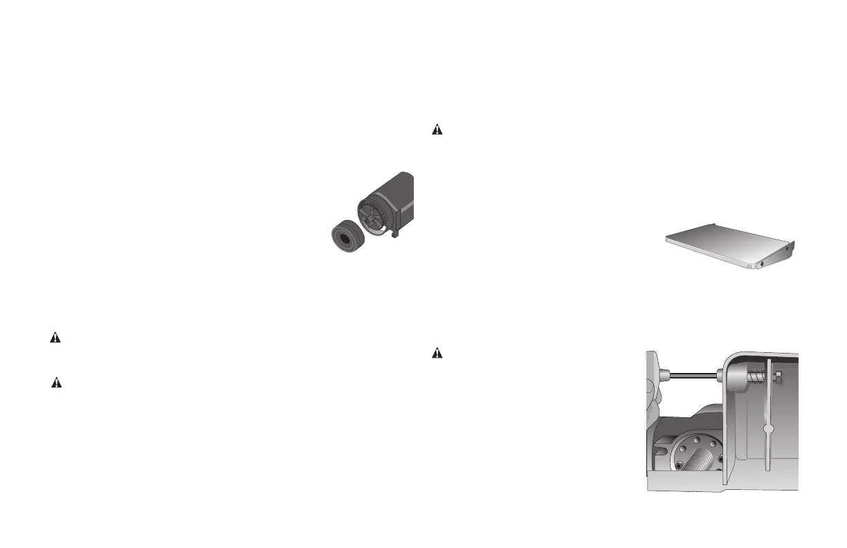
Chip Ejection Fan (Fig. 24)
The chip ejection fan on your planer should be cleaned
or cleared of debris periodically.
NOTE: TURN OFF AND UNPLUG THE PLANER PRIOR
TO ACCESSING THE CHIP EJECTION FAN.
TO ACCESS THE FAN
1. Remove the top cover of the planer with the
T-wrench.
2. Remove the dust shroud (Fig. 15, 16) and place it aside.
3. Remove the screws around the fan housing.
4. Remove the fan housing and place it aside as shown. The fan will now
be exposed for cleaning.
See the Troubleshooting Guide for additional information.
WARNING: Be sure to properly attach the fan housing and assemble the
shroud and top cover correctly before using your planer again.
Accessories
WARNING: Since accessories, other than those offered by DeWALT,
have not been tested with this product, use of such accessories with
this tool could be hazardous. To reduce the risk of injury, only DeWALT
recommended accessories should be used with this product.
Recommended accessories for use with your tool are available at extra cost
from your local service center. If you need any assistance in locating any
accessory, please contact Stanley Black & Decker, 82 Taryn Drive, Epping,
VIC 3076 Australia or call 1800 444 224 or (NZ) 0800 339 258.
Four accessories are available for the DW735 Thickness Planer.
Fig. 24
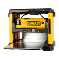
DW7351 Accessory Folding Tables (Fig. 25)
WARNING: For your own safety, read the tool instruction manual before
attaching the tables. Failure to heed these warnings may result in personal
injury and serious damage to the planer and the accessory. When servicing
this tool, use only identical replace ment parts. Have damaged cords
replaced by an authorized service center.
Your DW7351 folding table box should
include:
2 folding tables 4 cap screws
4 springs 4 nuts
4 stepped bolts
Set-up and Installation of
Base Hardware (Fig. 26–28)
1. Place planer on a secure table or workbench. Position planer so the front
75-100mm (3–4") of the base can be accessed from the underside.
2. Secure the rear of the planer to the table/bench with nails or screws to
prevent it from tilting or falling from the table.
WARNING: The planer could tilt or fall
from the table if it is not properly secured
opposite the end where the folding table is
being installed. Serious injury may result.
3. Place the spring onto the small end of
the stepped bolt.
4. Insert the end of the bolt with the
spring around it into the larger hole on
the side of the base.
5. Push the stepped bolt all the way
Fig. 25
Fig. 26