사양
입력
...........................220V AC ,
7.5 Amp
무부하 속도..............10,000 RPM
이송 속도..................4.3m/mim (14’/min)또는 7.0m/min(26’/min)
깎는 높이..................최대 150mm(6
”
), 최소 3mm(1/8
”
)
깎는 너비..................최대 330mm(13
”
)
깎는 깊이..................최대 3mm(1/8
”
) (보드의 경우 150 mm(6
”
) 이하의 너비)
전기 연결
전원공급장치가 명판에 표시된 것과 맞는지 확인해보십시오. 볼트, 50/60 Hz, “교류만”
이라는 것은 본 자동대패를 직류가 아니라 교류로만 작동시켜야 함을 의미합니다. 10 %
이상 전압이 감소하면 전력이 소실되어 과열될 것입니다. 모든 DEWALT 전동공구는 공
장에서 시험했습니다. 전동공구가 작동하지 않는다면, 전원 공급 장치를 확인해보십시오.
자동대패 포장 풀기
모든 부품이 들어 있는지 자동대패 상자의 내용물을 확인하십시오. 본 사용설명서
자동대패 1개
외에
도 다음 부품들이 들어있어야 합니다.
·
· 깊이 조정 크랭크 손잡이 1개
· 둥근 먼지 흡입구 1개
자동대패 운반하기
경고: 안전을 위해서, 두 명이 이 공구를 옮기는 것을 권장합니다.
17
그렇지 않으면 크게 다칠 수 있습니다. 평삭기를 움직일 때, 측면의 이동 손잡이(A)나 평
삭기 밑부분의 손잡이(B)를 잡고 옮기십시오. 평삭기를 운반하거나 보관할 때, 코드를 적
당하게 감아두도록 전동공구 뒤쪽에 있는 코드랩(C)을 이용하십시오.
작업대에 고정하기
작업대에 쉽게 고정하기 위해, 자동대패의 4 귀퉁이에 각각 다른 크기의 두 개의 구
이 있습니다. 자동대패를 볼트로 고정한다면, 큰 구멍을 이용하십시오. 자동대패를
이용할 필요는 없습니다. 움직이지 않도록 평삭기를 항상 확실하게 고정하십시오.
못이나 나사로 고정한다면, 작은 구멍을 이용하십시오. 두 가지 크기의 구멍을 모두
전동공구의 이 동성을 용이하게 하도록, 작업 지지대에 조여질 수 있거나 다른 작업대로
옮겨 다시 조일 수 있는 12.7mm(1/2’’) 이상의 합판에 고정할 수 있습니다.
멍(D)
주:
자동대패를 합판 조각에 고정하기로 했다면, 고정 나사가 목재의 바닥에서 튀어나오
자동대패를 합판 조각에 고정하기로 했다면, 고정
지 않는지 확인하십시오. 합판은 작업 지지대와 동일 평면에 있어야 합니다.
주의:
나사가 목재의 바닥에서 튀어나오지 않는지 확인하십시오.
합판은 작업 지지대와 동일 평면에 있어야 합니다.
조립
경고:
가드(E)를 제거하지 마십시오. 크게 다칠 수
있습니다. 전원이 꺼진 상태인지 확인하십시오.
깊이 조정 크랭크 손잡이를 장착하려면
1. 크랭크 손잡이 자루에 있는 육각볼트를 제거
하십시오.
2. 크랭크 손잡이(F)를 자루에 넣으십시오.
3. 육각볼트와 T형 렌치(G)를 제 위치에 고정하십시오.
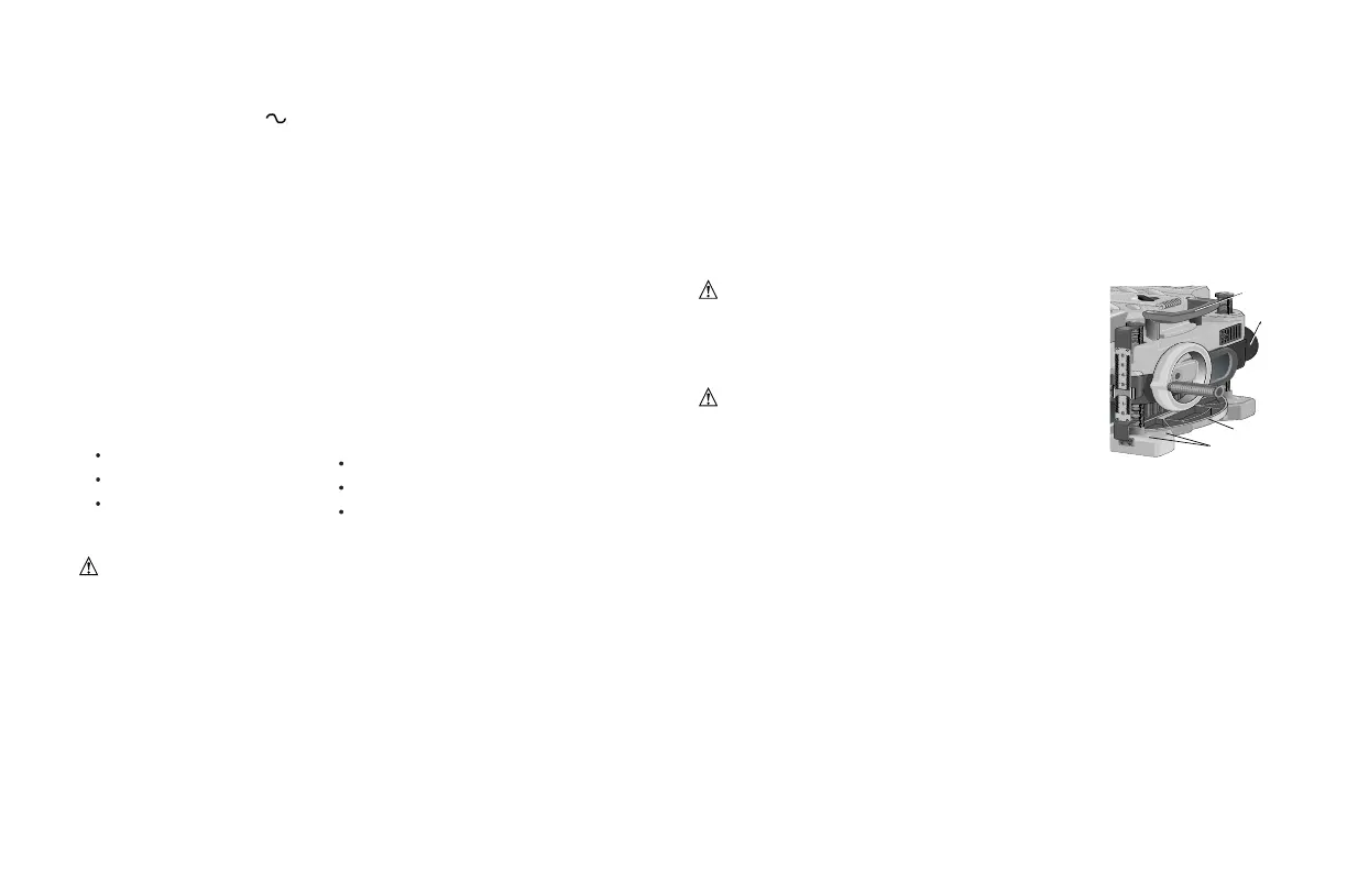
먼지 배출구
자동대패에는 별도로 두 개의 먼지 배출구가 들어있습니다. 아래 보는 바와 같이 둥근 흡
입구(I)는 100mm(4’’) 집진호스에 사용합니다. 길고 편평한 흡입구(J)는 집진기를 사용하
지 않을 때 부착해야 합니다.
먼지 배출구 설치하기
1. 사용하려는 집진기에 맞는 흡입구(I 또는 J)를 선택하십시오.
·
길고 편평한 먼지 흡입구 1개
·
T형 렌치(공구의 위쪽 뚜껑에 있음) 1개
·
크랭크 손잡이용 육각볼트 1개
4
Your risk from these exposures varies, depending on how often you do this type of
work. To reduce your exposure to these chemicals: work in a well ventilated area, and
work with approved safety equipment, such as those dust masks that are specially
designed to filter out microscopic particles.
• Avoid prolonged contact with dust from power sanding, sawing, grinding,
drilling, and other construction activities. Wear protective clothing and wash
exposed areas with soap and water. Allowing dust to get into your mouth, eyes,
or lay on the skin may promote absorption of harmful chemicals.
CAUTION: A dust mask or respirator should be worn by all persons entering the
work area. The filter should be replaced daily or whenever the wearer has difficulty
breathing. See your local hardware store for the proper approved dust mask.
SPECIFICATIONS
Input.................................240V AC , 7.5 Amp
No load speed .................10,000 RPM
Feed speed.......................4.3 m/min (14’/min) or 7.0 m/min (26’/min)
Planing height ..................Maximum 150mm (6”), Minimum 3mm(1/8”)
Planing width...................Maximum 330mm (13”)
Planing depth...................
Maximum 3mm (1/8”)(for boards 150mm (6”) wide or less)
ELECTRICAL CONNECTION
Be sure your power supply agrees with the nameplate marking. Volts, 50/60 Hz or
“AC only” means your planer must be operated only with alternating current and never
with direct current. Voltage decrease of more than 10% will cause loss of power and
overheating. All D
EWALT tools are factory tested, if this tool does not operate, check the
power supply.
UNPACKING YOUR PLANER
Check the contents of your planer carton to make sure that you have received all parts.
In addition to this instruction manual, the carton should contain:
• 1 Planer • 1 Depth adjustment crank handle
• 1 Round Dust Port • 1 Long, Flat Dust Port
• 1 T-wrench (located in • 1 Allen screw for
the top cover of the unit) Crank Handle
TRANSPORTING THE PLANER
WARNING: For your own safety, it is recommended people carry this machine or
serious injury could result. When moving your planer, carry it either by the side car-
rying handles (A) or by the handles at the base of the planer (B). When transporting or
storing the planer, use the cord wrap located in the back of the tool (C) to keep the cord
in place.
BENCH MOUNTING
To facilitate bench mounting, two different sized holes (D) are provided on the
four corners of your planer. If mounting the planer with bolts, use the larger
holes. If mounting the planer with nails or screws, use the smaller holes. It is
not necessary to use both sets of holes. Always mount your planer firmly to
prevent movement. To enhance the tool’s portability, it can be mounted to a
piece of 12.7mm(1/2” ) or thicker plywood which can then be clamped to your
work support or moved to other job sites and reclamped.
NOTE: If you elect to mount your planer onto a piece of plywood, make sure
that the mounting screws don’t protrude from the bottom of the wood. The
plywood must sit flush on the work support.
CAUTION: The mounting surface should not be
warped or otherwise uneven.
ASSEMBLY
WARNING: DO NOT REMOVE GUARDS (E).
Serious injury could result.
TO ATTACH THE DEPTH ADJUSTMENT CRANK
HANDLE
1. Remove the Allen screw located in the crank
handle shaft.
2. Insert the crank handle (F) over the shaft.
3. Secure in place with the Allen screw and T-wrench (G) provided.
DUST EJECTION PORTS
Your planer comes with two separate dust ejection ports. The round port
(I) as shown below is for use with a 100mm (4” ) dust collector hose. The
long, flat port (J) should be attached when no dust collector will be used.
TO SET UP DUST EJECTION
1. Select the port (I or J) that suits the type of dust collector you will be
using.
D
A
B
2. 부스러기 배출슈트(H)의 잠금 버튼(K)을누르십시오.
3. 먼지 흡입구의 새김눈을 부스러기 배출슈트의 핀으로 슬슬 움직이십시오.
4. 버튼이 배출슈트에 맞아 적당한 위치에 잠길 때까지 흡입구를 돌리십시오.
 Loading...