5
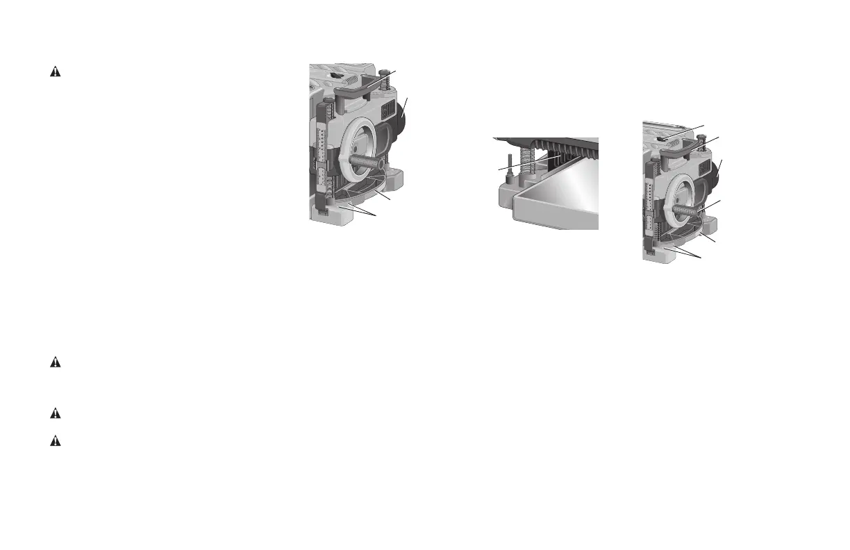
Transporting the Planer (Fig. 1)
Warning: For your own safety, it is
recommended that two people carry this
machine or serious injury could result.
When moving your planer, carry it either by the side
carrying handles (A) or by the handles at the base of
the planer (B). When transporting or storing the
planer, use the cord wrap located in the back of
the tool (C) to keep the cord in place.
Bench Mounting (Fig. 1)
To facilitate bench mounting, two different sized
holes (D) are provided on the four corners of your
planer. If mounting the planer with bolts, use the
larger holes. If mounting the planer with nails or
screws, use the smaller holes. It is not necessary to use both sets of holes.
Always mount your planer firmly to prevent movement. To enhance the
tool’s portability, it can be mounted to a piece of 12.7mm (1/2") or thicker
plywood which can then be clamped to your work support or moved to
other job sites and reclamped.
NOTE: If you elect to mount your planer onto a piece of plywood, make
sure that the mounting screws don’t protrude from the bottom of the wood.
The plywood must sit flush on the work support.
CAUTION: The mounting surface should not be warped or otherwise
uneven.
ASSEMBLY
WARNING: DO NOT REMOVE GUARDS (E, Fig. 2). Serious injury could
result.
WARNING:To reduce the risk of serious personal injury, turn
tool off and disconnect tool from power source before making any
adjustments or removing/installing attachments or accessories. An
accidental start-up can cause injury.
D
A
B
C
Fig. 1
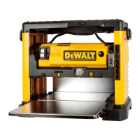
TO ATTACH THE DEPTH ADJUSTMENT CRANK HANDLE (FIG. 3)
1.Remove the screw located in the crank handle shaft.
2.Insert the crank handle (F) over the shaft.
3.Secure in place with the screw and T-wrench (G) provided.
e
Fig.2
D
a
b
c
g
F
Fig.3
DUST EJECTION PORTS (FIG. 4)
Your planer comes with a dust ejection port. The round port (I) as shown
below is for use with a dust collector hose no less than 200mm (8") in
length.
TO SET UP DUST EJECTION (FIG. 4)
1.Select the port (I or J) that suits the type of dust collector you will be
using.
3.Slide the notches in the dust port over the pins on the chip
ejection chute.
4.Rotate the port until the button engages the dust ejection chute and
locks in place.