(grounded) n .........................rated speed
................... Class II Construction .......................earthing terminal
(double insulated)
........................safety alert symbol
…/min ............per minute BPM ...................beats per minute
IPM .................impacts per minute RPM ...................revolutions per minute
SPM ...............strokes per minute sfpm ...................surface feet per minute
SAVE THESE INSTRUCTIONS FOR FUTURE USE
Motor
Be sure your power supply agrees with the nameplate marking. Voltage decrease of more than
10% will cause loss of power and overheating. D
EWALT tools are factory tested; if this tool does
not operate, check power supply.
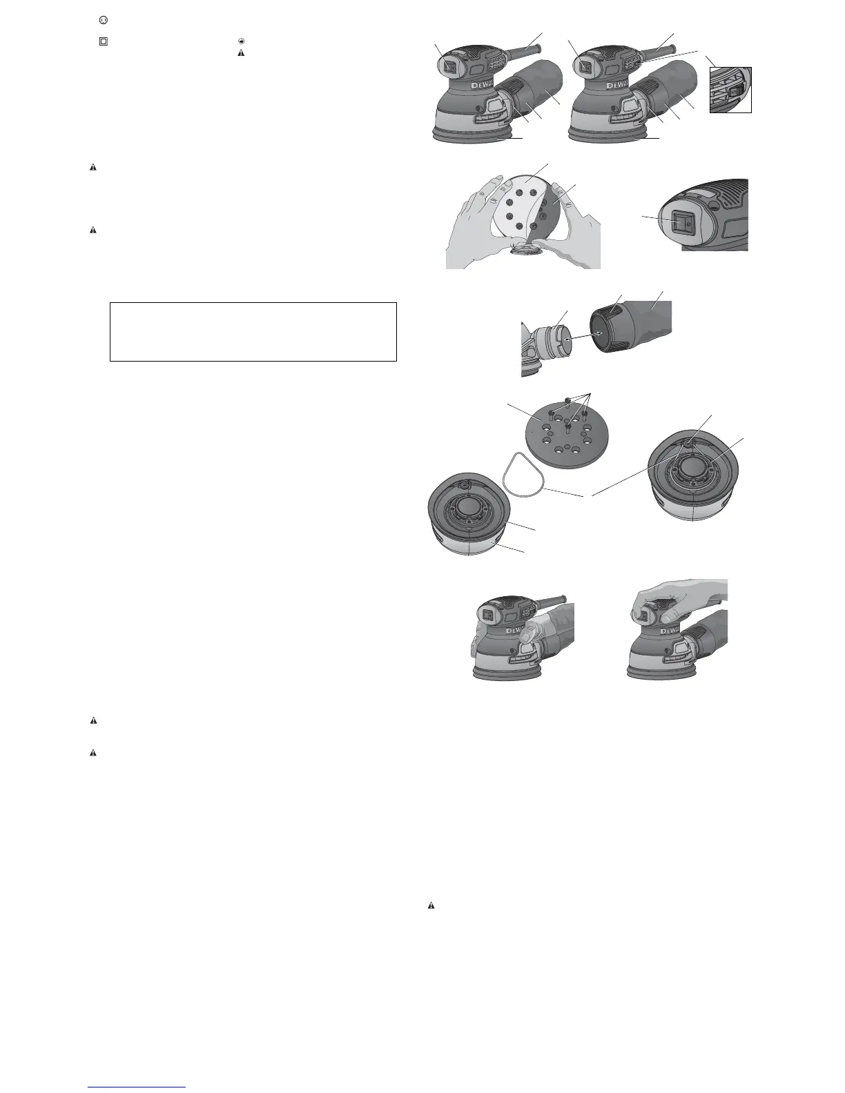
COMPONENTS (FIG. 1)
WARNING: Never modify the power tool or any part of it. Damage or personal injury could result.
A. On/Off switch
B. Speed control dial (DWE6423)
C. Dust extraction outlet
D. Dust bag
E. Dust bag collar
F. Sanding pad
G. Strain relief
ASSEMBLY AND ADJUSTMENTS
WARNING: To reduce the risk of injury, turn unit off and disconnect it from power
source before installing and removing accessories, before adjusting or when making
repairs. An accidental start-up can cause injury.
Attaching Sanding Discs (Fig. 2)
Your sander is designed to use 5" (125 mm) sanding discs (H) with an 8-hole dust extraction
pattern. Sanding discs for the DWE6421 and DWE6423 attach with hook and loop. Sanding discs
for the DWE6420 attach using pressure sensitive adhesive (PSA).
REQUIRED SANDPAPERS
Model Sander Disc Size Attachment Method Hole Pattern
DWE6420 5” PSA 8 Holes
DWE6421 5” Hook & Loop 8 Holes
DWE6423 5” Hook & Loop 8 Holes
TO ATTACH SANDING DISC TO THE SANDING PAD (FIG. 2)
1. Turn the sander over so that the sanding pad (F) is facing upward.
2. Clean the dust from the sanding pad (F) face.
3. Hold the pad with one hand to keep it from rotating.
4. With the other hand, align the holes and place the disc (H) directly on top of the pad.
NOTE: These sanders are not to be used in drywall applications. Using a sanding screen (e.g.,
screen used for sanding drywall) directly on the hook and loop pad will not hold and will damage
the hooks on the pad. The hooks on the pad will wear very rapidly if left in contact with the work
surface while the tool is operating.
Switch (Fig. 3)
To turn the unit on, depress the side of the dust-protected switch (A) that corresponds to the
symbol “I”. To turn the tool off, depress the side of the switch that corresponds to the symbol “O”.
Speed Control Dial (Fig. 1)
DWE6423
The speed control dial (B), shown in Figure 1, allows you to increase or decrease speed from 8,000–
12,000 Orbits Per Minute. The optimal speed setting for each application is very much dependent
on personal preference. Generally, you will want to use a higher setting on harder materials and a
lower setting on softer materials. Material removal rate increases as speed increases.
Dust Extraction (Fig. 4, 5)
Your sander has two dust extraction methods: a built-in outlet (C) which allows either the supplied
dust bag (D) or a shop vacuum system to be connected; and a dust skirt (M, Fig. 5). The built-in
outlet utilizes the D
EWALT AirLock connection making it compatible with the DEWALT dust extractor.
TO ATTACH THE DUST BAG
1. While holding the sander, fit the dust bag collar (E) to the outlet (C) as shown in Figure 4.
2. Turn the collar (E) clockwise to lock the dust bag (D) in place.
TO EMPTY THE DUST BAG
1. While holding the sander, turn the collar (E) counterclockwise to unlock the dust bag (D).
2. Remove dust bag from the sander and gently shake or tap the dust bag to empty.
3. Reattach the dust bag back onto the outlet and lock into place by turning the dust bag collar
clockwise.
You may notice that all the dust will not come free from the bag. This will not affect sanding
performance but will reduce the sander’s dust collection efficiency. To restore your sander’s dust
collection efficiency, depress the spring inside the dust bag when you are emptying it and tap it on
the side of the trash can or dust receptacle.
CAUTION: Never operate these tools unless the dust collector is in place. Sanding dust
exhaust may create a breathing hazard.
OPERATION (FIG. 6)
WARNING: To reduce the risk of injury, turn unit off and disconnect it from power
source before installing and removing accessories, before adjusting or when making
repairs. An accidental start-up can cause injury.
NOTICE: These sanders are not to be used in drywall applications.
NOTICE: Avoid overloading your sander. Overloading will result in a considerable reduction in
speed and finish quality of your work. The unit may also become hot. In this event, run sander at a
no load condition for a minute or two.
NOTICE: If you wrap the cord around the tool when you store it, leave a generous loop of cord
such that the strain relief (G) does not bend. This helps prevent premature cord failure.
To operate your sander, grasp it as shown in Figures 6A or 6B and turn it on. Move the unit in long,
sweeping strokes along the surface being sanded, letting the sander do the work.
Pushing down on the tool while sanding actually slows the removal rate and produces an inferior
quality surface. Be sure to check your work often, this sander is capable of removing material
rapidly, especially with coarse paper.
The random orbital action of your sander allows you to sand with the grain or at any angle across
it for most sanding jobs. To produce the best finish possible, start with coarse grit sandpaper and
change gradually to finer and finer paper. Vacuum and wipe surface with a tack cloth between grit
steps. Your sander is designed to sand into small or confined areas. Its small size and light weight
make it ideal for overhead work.
The rate at which the dust collection bag fills up will vary with the type of material being sanded
and the coarseness of the sandpaper. For best results, empty the bag frequently. When sanding
painted surfaces, (see the following for additional precautions when sanding paint) you may find that
the sandpaper loads up and clogs with paint. A heat gun will work much better to remove paint
before sanding. FOLLOW ALL SAFETY INSTRUCTIONS IN HEAT GUN INSTRUCTION MANUAL.
NOTE (DWE6420 ONLY): When using PSA sanding discs, remove the disc soon after operation.
PSA paper, if the disc is left on during tool storage, sometimes becomes difficult to remove. To aid
in the removal of old PSA paper, sand for a few minutes to soften the adhesive backing prior to
changing disc.
Precautions To Take When Sanding Paint
1. Sanding of lead based paint is NOT RECOMMENDED due to the difficulty of controlling the
contaminated dust. The greatest danger of lead poisoning is to children and pregnant women.
2. Since it is difficult to identify whether or not a paint contains lead without a chemical analysis, we
recommend the following precautions when sanding any paint:
PERSONAL SAFETY
1. No children or pregnant women should enter the work area where the paint sanding is being
done until all clean up is completed.
FIG. 3
FIG. 2
2. A dust mask or respirator should be worn by all persons entering the work area. The filter
should be replaced daily or whenever the wearer has difficulty breathing. See your local
hardware store for the proper NIOSH-approved dust mask.
3. NO EATING, DRINKING or SMOKING should be done in the work area to prevent ingesting
contaminated paint particles. Workers should wash and clean up BEFORE eating, drinking
or smoking. Articles of food, drink, or smoking should not be left in the work area where
dust would settle on them.
ENVIRONMENTAL SAFETY
1. Paint should be removed in such a manner as to minimize the amount of dust generated.
2. Areas where paint removal is occurring should be sealed with plastic sheeting of 4 mils
thickness.
3. Sanding should be done in a manner to reduce tracking of paint dust outside the work area.
CLEANING AND DISPOSAL
1. All surfaces in the work area should be vacuumed and thoroughly cleaned daily for the
duration of the sanding project. Vacuum filter bags should be changed frequently.
2. Plastic drop cloths should be gathered up and disposed of along with any dust chips or
other removal debris. They should be placed in sealed refuse receptacles and disposed of
through regular trash pick-up procedures. During clean up, children and pregnant women
should be kept away from the immediate work area.
3. All toys, washable furniture and utensils used by children should be washed thoroughly
before being used again.
MAINTENANCE
WARNING: To reduce the risk of injury, turn unit off and disconnect it from power
source before installing and removing accessories, before adjusting or when making
repairs. An accidental start-up can cause injury.
Replacing the Sanding Pad and the Belt (Fig. 5)
Your sander is equipped with a replaceable belt (L) which is located between the pad (F) and the
sander body (I). It is designed to control the pad speed while the unit is off the work surface. The
belt and the sanding pad (F) are designed to be consumable parts and will occasionally need to be
replaced. The sanding pad needs replacement when signs of wear become evident. Replacement
of the belt is necessary when the pad speed increases very dramatically when the unit is lifted
from the work surface. These parts are available at extra cost from your local dealer or authorized
D
EWALT service center.
1. Holding the platen firmly, remove the four screws (N) from the bottom of the pad.
2. Remove the pad (F).
3. Replace worn or damaged belt (L) by wrapping it around the shoulder screw (J) and bearing
retainer (K) as shown in Figure5.
4. Reinstall pad (replace with new pad if necessary). Replace the four screws (N). Be careful not
to over-tighten screws.
FIG. 1
A
H
DWE6420, DWE6421
FIG. 6A
FIG. 6B
DWE6423
A
F
E
D
A
F
E
D
B
E
FIG. 4
C
G
G
C
C
F
D
FIG. 5
I
F
J
K
M
L
N

 Loading...